Heat insulating structure of pipeline

A heat insulation structure and pipeline technology, which is applied in pipeline protection, heat exchange equipment, pipeline protection through heat insulation, etc., can solve the problems of high assembly cost and complicated process

Pending Publication Date: 2018-08-17
重庆三二一绝热制品有限公司
View PDF0 Cites 0 Cited by
  • Summary
  • Abstract
  • Description
  • Claims
  • Application Information

AI Technical Summary

Problems solved by technology

[0003] In order to solve the problems of complex procedures and high assembly costs in the existing pipeline heat insulation structure, the present invention provides a...

Method used


Image

  • Heat insulating structure of pipeline
  • Heat insulating structure of pipeline

Examples


Embodiment Construction

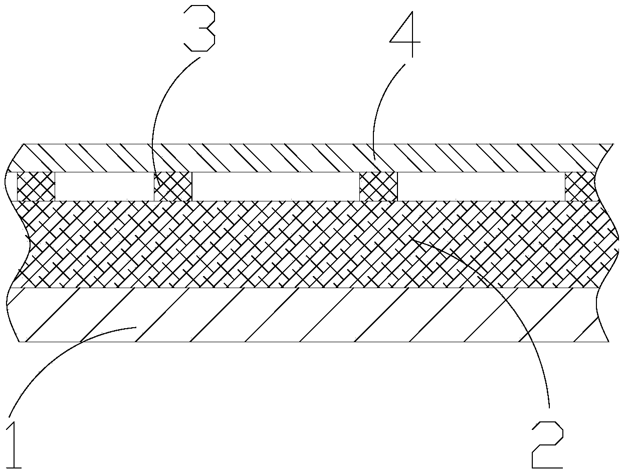
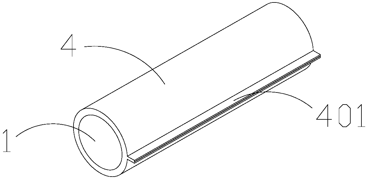
[0016] In order to make the purpose, technical solution and advantages of the present application clearer, the present invention will be further described in detail below in conjunction with the accompanying drawings and embodiments. It can be seen from the figure that a pipeline heat insulation structure includes a basic pipe 1, and an inner sheath 2, a connecting layer 3 and an outer sheathing 4 are sequentially arranged along the wall of the basic pipe 1 from the inside to the outside; the connecting layer 3 is two Or two or more metal strips arranged side by side, one side of the metal strip is welded to the outer sheath 4, and the other side of the metal strip is nailed or riveted to the inner sheath 2; the outer sheath 4 is uniformly provided with concave and convex parts , that is, a depression is provided on one side of the outer sheath 4, and a protrusion is provided on the other side of the outer sheath 4 corresponding to the depression, and the joints at both ends of...


PUM

PropertyMeasurementUnit
Thicknessaaaaaaaaaa
Thicknessaaaaaaaaaa

Abstract

The invention provides a heat insulating structure of a pipeline in order to solve the problems that an existing heat insulating structure of the pipeline is complicated in procedure and high in assembly cost. The heat insulating structure of the pipeline comprises a foundation pipe, and an inner protection layer, a connection layer and an outer protection layer are sequentially arranged along thewall of the foundation pipe from inside to outside. The connection layer is two or more metal straps arranged in parallel, one sides of the metal straps are connected with the outer protection layerin a welded mode, and the other sides of the metal straps are in nailed or riveted connection with the inner protection layer. The outer protection layer is evenly provided with concave-convex parts,that is, pits are formed in one side of the outer protection layer, protrusions corresponding to the pits are arranged on the other side of the outer protection layer, and joints of the two ends of the outer protection layer are connected in a welded mode. By means of the heat insulating structure of the pipeline, the step of manually wrapping the pipeline with the inner protection layer is omitted, time is shortened, the assembly efficiency is improved, the assembly cost is reduced, and meanwhile the product quality is ensured.

Description

technical field [0001] The invention relates to a thermal insulation structure, in particular to a pipeline thermal insulation structure. Background technique [0002] Existing pipeline insulation generally uses insulation materials wrapped outside the pipeline. The commonly used wrapping method is to first cut the insulation material to match the size of the pipeline, and then fix the insulation material with high-temperature cloth by manual wrapping. , the outer side of the high-temperature cloth is fixed by stainless steel materials; due to many irregular pipelines, the manual wrapping process is time-consuming and long, resulting in not only complicated procedures during the installation of this structure, but also high difficulty in operation, especially the use of high-temperature cloth for heat insulation materials During fixing, it is easy to have uneven wrapping on the outer wall of the pipeline, resulting in poor cooling effect. Therefore, this structure has the p...

Claims


Application Information

Patent Timeline
IPC IPC(8): F16L59/02F16L59/05F16L59/10
CPCF16L59/029F16L59/028F16L59/04F16L59/10
Inventor 余海张远坤张和贵
Owner 重庆三二一绝热制品有限公司
Why Eureka
Try Eureka