
Anti-Compton and anti-cosmic-ray high purity germanium spectrometer

A cosmic ray and anti-Compton technology, applied in X-ray energy spectrum distribution measurement, etc., can solve the problems of large overall volume of high-purity germanium spectrometers, increase equipment cost, and difficulty in achieving large volumes, etc., to achieve small volume, The effect of easy operation, high efficiency and figure of merit measurement

Pending Publication Date: 2018-08-17
上海新漫传感科技有限公司
View PDF7 Cites 3 Cited by
  • Summary
  • Abstract
  • Description
  • Claims
  • Application Information

AI Technical Summary

Problems solved by technology

The existing technology only has a single anti-Compton spectrometer or anti-cosmic ray spectrometer, and the two technologies cannot be realized on the same equipment, and the spectrum with low background and low Compton plateau cannot be obtained, which increases the use of equipment cost
Because high-purity germanium spectrometers need to be equipped with heavy low-background lead chambers, especially anti-coincidence lead chambers, it is often time-consuming and laborious to use
In the prior art, NaI detectors are often used as ring detectors. NaI detectors are difficult to achieve large volumes and are prone to deliquescence.
In addition, the existing high-purity germanium spectrometer installs the ring detector and the main detector in the lead shielding room body, and installs the top detector in the upper lead cover. The overall volume of the high-purity germanium spectrometer is relatively large

Method used


Image

  • Anti-Compton and anti-cosmic-ray high purity germanium spectrometer
  • Anti-Compton and anti-cosmic-ray high purity germanium spectrometer
  • Anti-Compton and anti-cosmic-ray high purity germanium spectrometer

Examples


Embodiment Construction

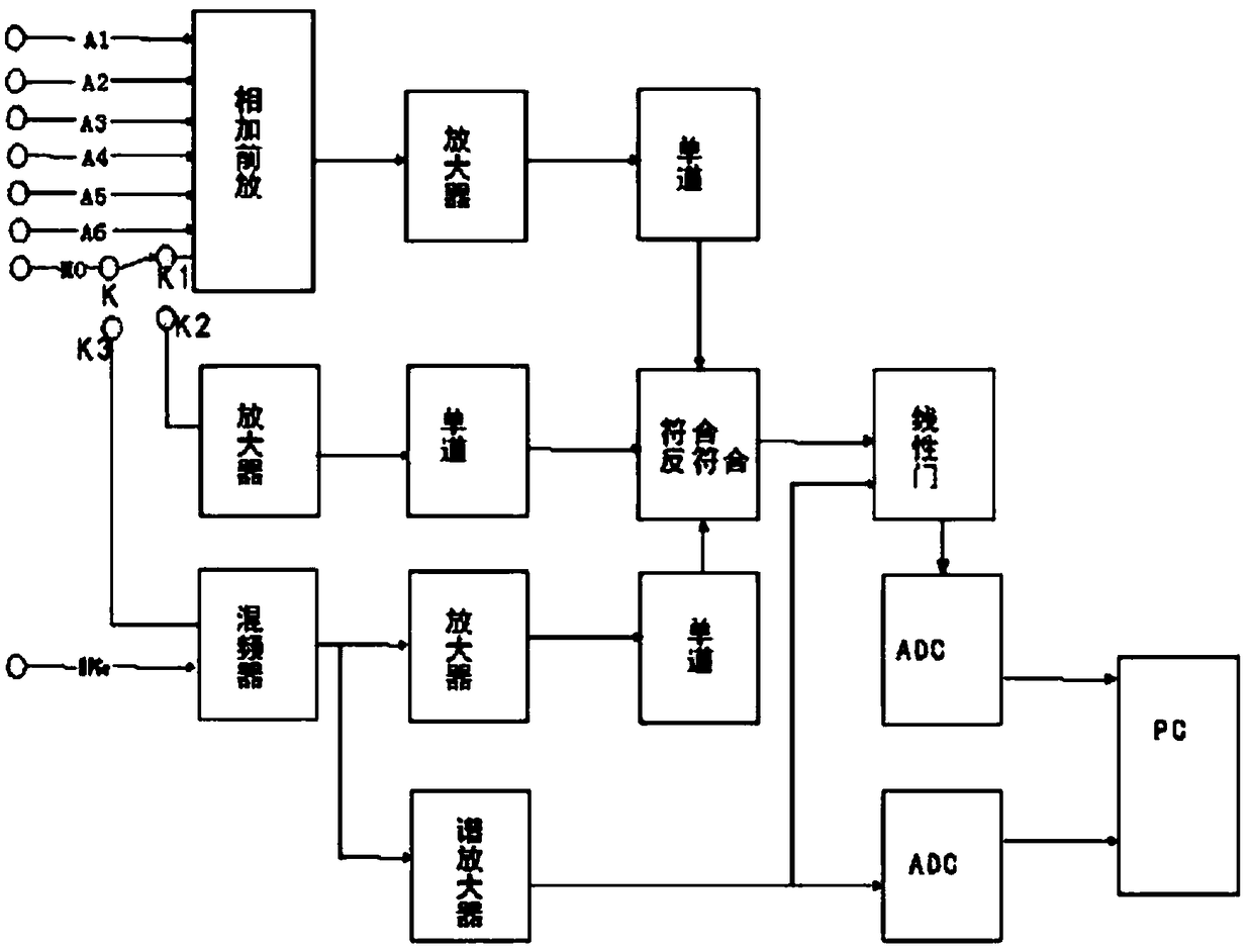
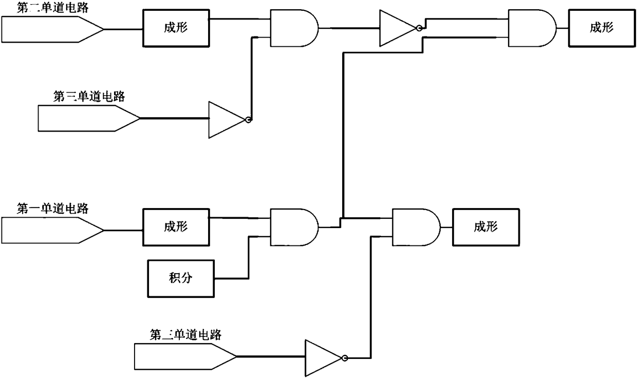
[0023] The following is attached Figures 1 to 5 The given examples further illustrate the specific implementation of the anti-Compton anti-cosmic ray high-purity germanium spectrometer of the present invention. The anti-Compton anti-cosmic ray high-purity germanium spectrometer of the present invention is not limited to the description of the following examples.

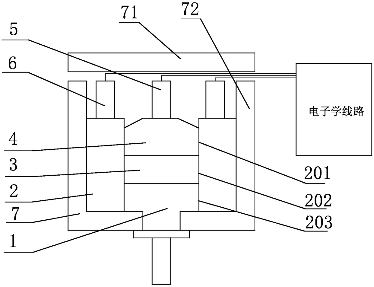
[0024] Such as figure 1As shown, an anti-Compton anti-cosmic ray high-purity germanium spectrometer of the present invention includes a lead shielding room 7 and a main detector 1 installed in the lead shielding room 7, a ring detector 2 and a coincidence detector 4, and coincidence detection The detector 4 is located above the main detector 1; the ring detector 2 is a BG0 scintillator detector; the middle part of the ring detector 2 is provided with a cavity, and the upper part of the cavity forms a first installation for installing the detector 4. Cavity 201, the lower part of the cavity forms a third installati...


PUM


Abstract

The invention provides an anti-Compton and anti-cosmic-ray high purity germanium spectrometer comprising a lead shielding room and a main detector, a ring detector and a coincidence detector which areinstalled in the lead shielding room. The coincidence detector is arranged above the main detector. The ring detector is a BGO scintillator detector. The middle part of the ring detector is providedwith a cavity. A first installing cavity used for installing the coincidence detector is formed on the upper part of the cavity. A third installing cavity used for installing the main detector is formed on the lower part of the cavity. A second installing cavity used for placing the sample to be detected is formed in the middle part of the cavity. The BGO scintillator detector is used as the ringdetector so that the size is small and the ray detection efficiency is excellent. The ring detector, the coincidence detector and the main detector are arranged on the lower part of the lead shieldingroom, the coincidence detector and the main detector are installed on the upper and lower ends of the middle cavity of the ring detector respectively, and the second installing cavity used for placing the sample to be detected is arranged between the coincidence detector and the main detector so that the arrangement space of the detectors is compact and the size can be reduced.

Description

technical field [0001] The invention relates to the technical field of radioactivity measurement, in particular to an anti-Compton anti-cosmic ray high-purity germanium spectrometer. Background technique [0002] When the gamma ray energy is within the energy range of hundreds of KeV to MeV, the area of ​​the Compton plateau in the energy spectrum measured by the single crystal detector is often relatively large, which makes it difficult to analyze the complex spectrum. The all-energy peak of the lower-energy gamma-ray is superimposed on the Compton plateau of the high-energy gamma energy spectrum. Due to the statistical fluctuation of the technology on the plateau, the accuracy of the area measurement of the all-energy peak of the low-energy gamma-ray is greatly affected, or it may not be possible at all. The all-energy peak of low-energy gamma rays cannot be found. The Compton scattering of high-energy rays tends to cause higher fluctuations of low-energy rays, and even s...

Claims


Application Information

Patent Timeline
Patent Type & Authority Applications(China)
IPC IPC(8): G01T1/36
CPCG01T1/36
Inventor 张文婷蓝云霞陈永林徐强汪加龙
Owner 上海新漫传感科技有限公司
Learn More