An oil metal particle detection device

A metal particle and detection device technology, which is applied in the direction of measuring device, geophysical measurement, radio wave measurement system, etc., can solve the problems of detection data lag, long detection cycle, excitation coil detection coil residual voltage is not zero, etc., to achieve Real-time automatic compensation, improving detection sensitivity and stability, and reducing the effect of residual voltage

Active Publication Date: 2019-10-18
ANHUI RONDS SCI & TECH INC CO
View PDF6 Cites 0 Cited by
  • Summary
  • Abstract
  • Description
  • Claims
  • Application Information

AI Technical Summary

Problems solved by technology

Among them, the offline detection has the following disadvantages: 1. The detection period is long, and oil samples need to be manually taken regularly; 2. The detection cost is high, and the detection data lags behind, which cannot meet the timeliness requirements
[0005] However, in actual use, it is impossible to wind two excitation coils with the same parameters. The actual two excitation coils are asymmetrical and unbalanced. This unbalance of the excitation coils will cause the residual voltage output by the detection coil to be non-zero.
However, if the residual voltage is too large, the particle signal will be submerged, which will affect the detection sensitivity and stability, and even lead to the inability to detect metal particles.

Method used


Image

  • An oil metal particle detection device
  • An oil metal particle detection device
  • An oil metal particle detection device

Examples


Embodiment Construction

[0035] Exemplary embodiments of the present disclosure will be described in more detail below with reference to the accompanying drawings. Although exemplary embodiments of the present disclosure are shown in the drawings, it should be understood that the present disclosure may be embodied in various forms and should not be limited by the embodiments set forth herein. Rather, these embodiments are provided for more thorough understanding of the present disclosure and to fully convey the scope of the present disclosure to those skilled in the art.

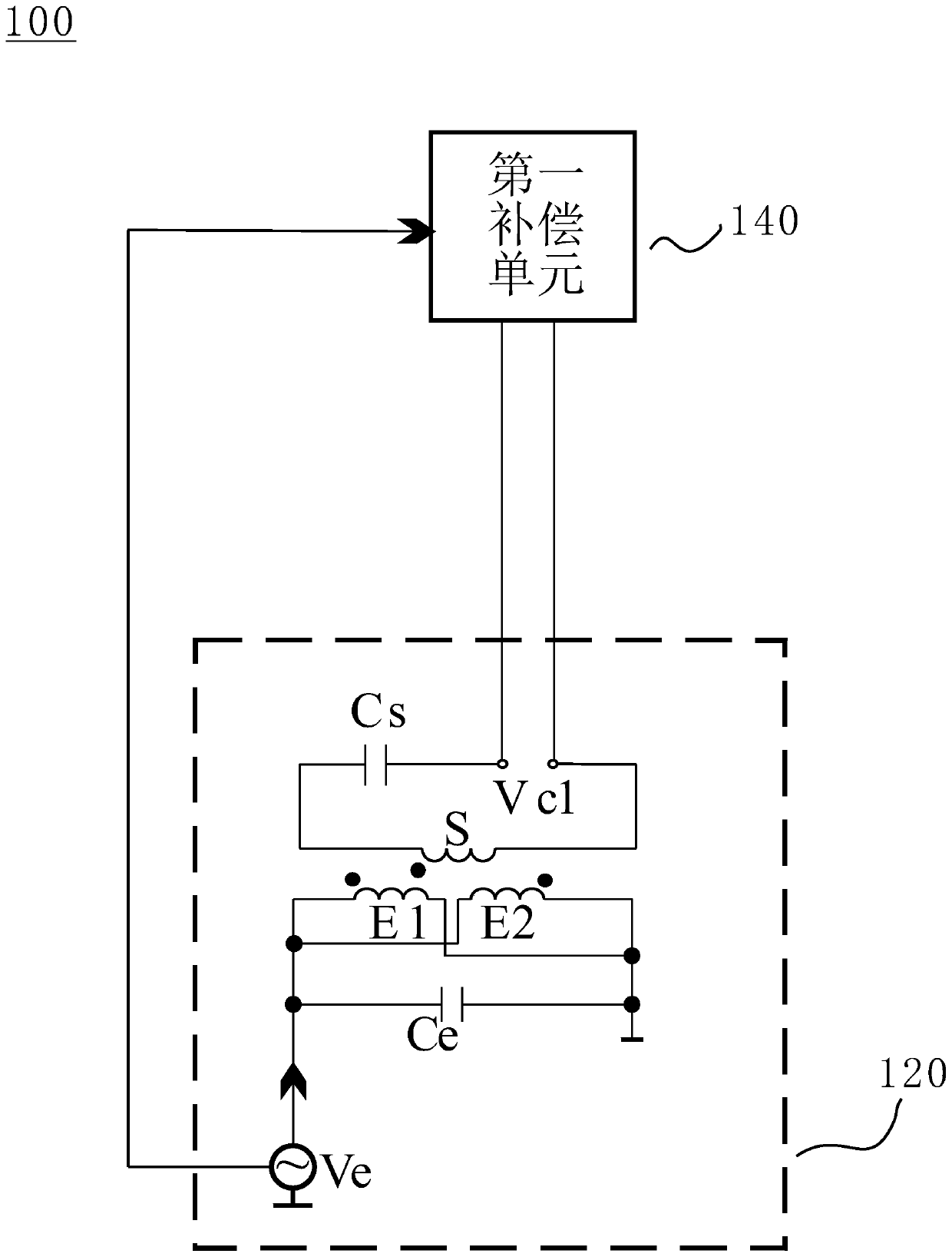
[0036] figure 1 A structural block diagram of an oil metal particle detection device 100 according to an exemplary embodiment of the present invention is shown. Such as figure 1 As shown, the oil metal particle monitoring device 100 includes a detection unit 120 and a first compensation unit 140 connected to the detection unit 120 .

[0037] The detection unit 120 includes an excitation signal source V e , detection coil S and t...


PUM


Abstract

The invention discloses an oil metal particle detection device comprising a detection unit and a first compensation unit. The detection unit comprises an excitation signal source, a detection coil, two excitation coils and a resonant matching capacitor. The excitation signal source is connected with the two excitation coils and the first compensation unit so as to provide excitation voltage to thetwo excitation coils and the first compensation unit. The two excitation coils are arranged on the two sides of the detection coil and have opposite winding directions. The detection coil is connected with the first compensation unit through the resonant matching capacitor and wound on the oil pipeline so that the metal particles can be detected according to the output voltage of the detection coil when the oil penetrates through the detection oil. The first compensation unit is suitable for receiving the excitation voltage from the excitation signal source and outputting the first compensation voltage so as to counteract the residual voltage of the detection coil.

Description

technical field [0001] The invention relates to the technical field of equipment state monitoring, in particular to an oil metal particle detection device. Background technique [0002] Today's mechanical equipment often has the characteristics of high precision and high speed, but this will bring the hazards of accelerated wear. Mechanical wear produces metal particles in the lubricating oil. Therefore, the detection of metal particles in oil is very important. It can effectively detect the wear state of equipment in real time and reflect the change process of equipment wear, so as to replace oil or replace related parts in time to prevent failures. [0003] At present, there are two detection methods for oil metal particles, namely offline and online. Among them, the offline detection has the following disadvantages: 1. The detection period is long, and oil samples need to be taken regularly manually; 2. The detection cost is high, and the detection data lags behind, whi...

Claims


Application Information

Patent Timeline
Patent Type & Authority Patents(China)
IPC IPC(8): G01V3/11G01N27/00
Inventor 任艺军冯志华刘斌
Owner ANHUI RONDS SCI & TECH INC CO
Why Eureka
Try Eureka