Buffer circuit applicable to two-way series load commutation switch of hybrid high-voltage direct-current circuit breaker

A high-voltage DC and buffer circuit technology, applied in electrical components, output power conversion devices, etc., can solve the problems of reducing reliability, high buffer capacitance, reducing the quickness of hybrid high-voltage DC circuit breakers, etc., to improve reliability. , the effect of reducing residual voltage and improving quickness

Active Publication Date: 2017-02-22
SICHUAN UNIV
View PDF3 Cites 0 Cited by
  • Summary
  • Abstract
  • Description
  • Claims
  • Application Information

AI Technical Summary

Problems solved by technology

The structure of the RCD circuit is simple, but during the opening process of the hybrid high-voltage DC circuit breaker, when the current-carrying branch switches to the solid-state main switch branch, the buffer capacitor will be discharged through the UFD, resulting in an increase in the breaking current of the UFD and a change in the separation time of the UFD contacts. Long, which reduces the quick action of the hybrid high-voltage DC circuit breaker; based on the improved buffer circuit of RCD, the discharge branch of the buffer capacitor through the UFD is removed, but after the hybrid high-voltage DC circuit breaker is opened, the buffer capacitor goes up. The residual voltage is high, which reduces the reliability of the hybrid high-voltage DC circuit breaker for multiple opening and closing actions in a short period of time

Method used


Image

  • Buffer circuit applicable to two-way series load commutation switch of hybrid high-voltage direct-current circuit breaker
  • Buffer circuit applicable to two-way series load commutation switch of hybrid high-voltage direct-current circuit breaker
  • Buffer circuit applicable to two-way series load commutation switch of hybrid high-voltage direct-current circuit breaker

Examples


Embodiment

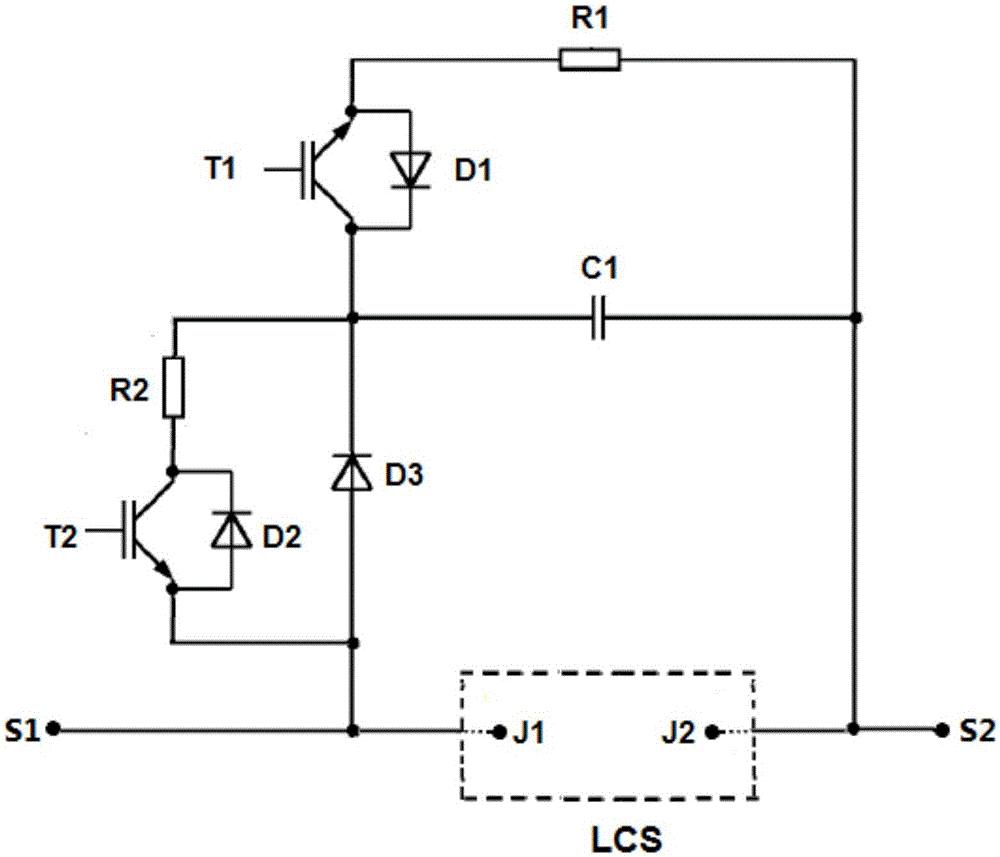
[0044] The specific embodiments of the present invention will be described below by taking the application of the hybrid high-voltage direct current circuit breaker of the present invention to a simple direct current system as an example. A simple 320kV / 2kA DC system such as Figure 6 As shown, in order to illustrate the specific connection relationship between the present invention and the bidirectional series LCS, only the specific structure of the bidirectional series LCS is drawn in detail in the figure, and the remaining components in the hybrid high voltage DC circuit breaker are simplified. Assume that the hybrid high-voltage DC circuit breaker closes at 0.02s, and the system operates normally after closing; at 0.1s, the system has a permanent DC fault, and the hybrid high-voltage DC circuit breaker opens after detecting the DC fault, and the fault is removed 0.06 s later, the hybrid high-voltage circuit breaker is closed again, and a DC fault is detected again after su...


PUM


Abstract

The invention discloses a buffer circuit applicable to a two-way series load commutation switch of a hybrid high-voltage direct-current circuit breaker and a control strategy. The one-way buffer circuit structure comprises a capacitor C1, insulated gate bipolar transistors T1 and T2, diodes D1, D2 and D3 and resistors R1 an R2. The collector and the emitter of the T1 are connected with the negative pole and the positive pole of the D1 respectively. One end of the R1 is connected with the emitter of the T1, and the other end of the R1 is connected with S2. The collector and the emitter of the T2 are connected with the negative pole and the positive pole of the D2 respectively. One end of the R2 is connected with the emitter of the T2, and the other end of the R2 is connected with the collector of the T1. The negative pole and the positive pole of the D3 are connected with the collector of the T1 and the collector of the T2 respectively. One end of the C1 is connected with the collector T1, and the other end of the C1 is connected with a node S2. The circuit control strategy includes the step of controlling the T1 and the T2 when the hybrid high-voltage direct-current circuit breaker is switched off and on. The circuit breaker is simple in structure and easy to control, and improves quick operation performance and reliability of the hybrid high-voltage direct-current circuit breaker.

Description

technical field [0001] The invention relates to a buffer circuit suitable for a bidirectional series load commutation switch (LCS) of a hybrid high-voltage direct current circuit breaker, belonging to the field of high-voltage direct current transmission. Background technique [0002] Voltage source converter based high voltage direct current (VSC-HVDC) based on power electronics technology has achieved vigorous development in large power grid interconnection and point-to-point power transmission due to its advantages of flexible power control and no commutation failure. Power transmission also provides a solution for the grid connection and consumption of rapidly developing new energy sources such as solar energy and wind energy with strong randomness. As one of the key technologies of DC transmission, HVDC circuit breakers are also the basis for the operation, control and protection of DC power grids. Hybrid HVDC circuit breakers are the most practical in HVDC systems bec...

Claims


Application Information

Patent Timeline
Patent Type & Authority Applications(China)
IPC IPC(8): H02M1/34
CPCH02M1/34H02M1/344
Inventor 王渝红刘程卓龚鸿王媛阳莉汶邹朋陈阳
Owner SICHUAN UNIV
Why Eureka
Try Eureka