Static sensitivity analysis method oriented to integrated electricity and gas system
A technology of integrated energy system and static sensitivity, applied in the field of electric-pneumatic coupled integrated energy system, can solve problems such as insufficient consideration
- Summary
- Abstract
- Description
- Claims
- Application Information
AI Technical Summary
Problems solved by technology
Method used
Image

Examples
Embodiment 1
[0045] A static sensitivity analysis method for electric-pneumatic coupled integrated energy systems, see figure 1 , the static sensitivity analysis method includes the following steps:
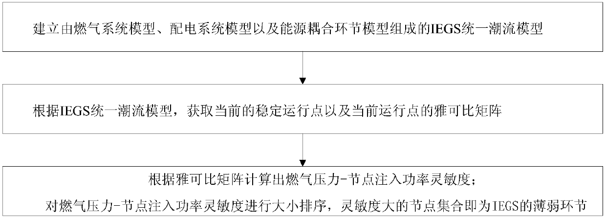
[0046] 101: Establish an IEGS unified power flow model consisting of a gas system model, a power distribution system model, and an energy coupling link model;
[0047] 102: Obtain the current stable operating point and the Jacobian matrix of the current operating point according to the IEGS unified power flow model;
[0048] 103: According to the Jacobian matrix, calculate the gas pressure-gas load sensitivity and the light gas turbine output-node injection power sensitivity, so as to calculate the gas pressure-node injection power sensitivity;
[0049] 104: Sorting the gas pressure-node injection power sensitivity, the node set with higher sensitivity is the weak link of IEGS.
[0050] In summary, the embodiment of the present invention considers the network status of the electricity-gas s...
Embodiment 2
[0052] Combined with the specific calculation formula, figure 2 1. The specific example further introduces the scheme in embodiment 1, see the following description for details:
[0053] 201: IEGS modeling;
[0054] The embodiment of the present invention takes IEGS including natural gas network (Natural Gas System, NGS), power distribution system (Power Distribution System, PDS) and coupling links as an example to verify the effectiveness of the method.
[0055] Among them, NGS is composed of gas source, gas pipeline, gas load, compressor, valve and so on. The valve is used to control the flow or cut-off of gas in the pipeline. It is assumed that the valve is only in two states: fully open or fully closed, so the network topology of NGS is determined. IEGS is connected to the large power grid through distribution transformers and it is assumed that IEGS has signed a power supply contract with the upstream power grid. The energy coupling link is a key link in the interacti...
Embodiment 3
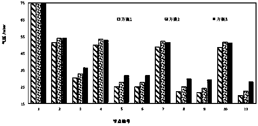
[0125] The following is a specific calculation example, combined with Figure 3-Figure 8 To verify the feasibility of the scheme in Examples 1 and 2, see the following description for details:
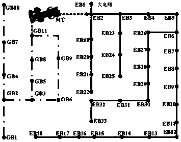
[0126] In order to verify the effectiveness of this method, a typical IEGS is taken as an example to illustrate the simulation. Such as image 3 As shown, the IEGS calculation example of the embodiment of the present invention is formed by coupling the IEEE-33 node power distribution system and the modified 11-node gas network through MT [13,17] , EBi and GBi represent grid nodes and gas nodes, respectively.
[0127] The distribution network is connected to the external large power grid through EB1. Assume that the electric power obtained by the distribution network and the external large power grid is 3500kW. At this time, EB1 is a PV node. MT connects GB11 of the gas network and EB2 of the distribution network as a balanced unit, so EB2 is the balance node of the distribution netw...
PUM
 Abstract
Description
Claims
Application Information
 - R&D Engineer
- R&D Manager
- IP Professional
- Industry Leading Data Capabilities
- Powerful AI technology
- Patent DNA Extraction
Browse by: Latest US Patents, China's latest patents, Technical Efficacy Thesaurus, Application Domain, Technology Topic.
© 2024 PatSnap. All rights reserved.Legal|Privacy policy|Modern Slavery Act Transparency Statement|Sitemap