Composite winding ironless linear permanent magnet synchronous motor

A permanent magnet synchronous motor and synthetic winding technology, applied in the shape/style/structure of synchronous machine parts, windings, winding conductors, etc., can solve the problems of large secondary eddy current loss, low power density, large thrust fluctuation, etc.

Active Publication Date: 2018-08-17
HARBIN INST OF TECH
View PDF5 Cites 12 Cited by
  • Summary
  • Abstract
  • Description
  • Claims
  • Application Information

AI Technical Summary

Problems solved by technology

[0004] The present invention aims to solve the problems of large thrust fluctuation, low power density, and large secondary eddy current loss in the linear permanent magnet synchronous motor with a double-sided secondary coreless structure used in the field of ultra-precision motion control. The present invention provides a A Synthetic Winding Coreless Linear Permanent Magnet Synchronous Motor

Method used


Image

  • Composite winding ironless linear permanent magnet synchronous motor
  • Composite winding ironless linear permanent magnet synchronous motor
  • Composite winding ironless linear permanent magnet synchronous motor

Examples


specific Embodiment approach 1

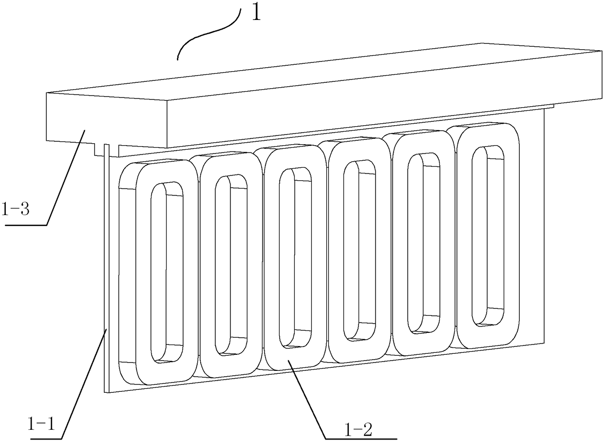
[0074] Specific implementation mode one: see figure Figure 1 to Figure 6 Describe this embodiment, the composite winding coreless linear permanent magnet synchronous motor described in this embodiment includes primary 1 and secondary 2;

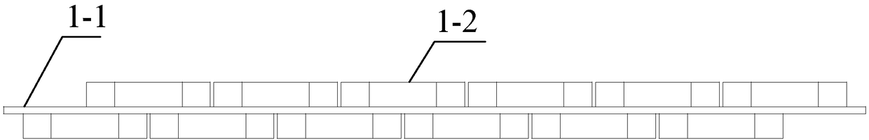
[0075] The primary 1 includes a primary substrate 1-1 and two sets of primary windings 1-2; the two sets of primary windings 1-2 are respectively arranged on the left and right sides of the primary substrate 1-1, and the corresponding phase windings of the two sets of primary windings 1-2 are connected in series, And along the direction of motion, there is a phase difference between the corresponding phase windings of the two sets of primary windings 1-2;

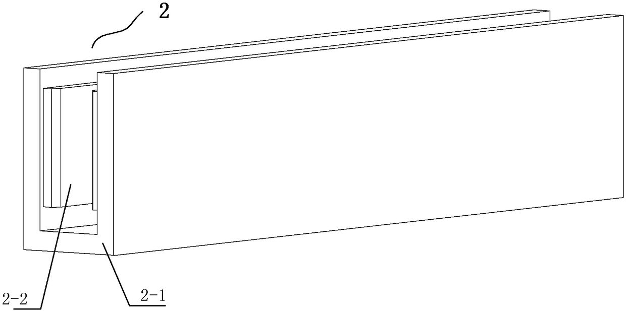
[0076] The secondary 2 is a U-shaped bilateral structure, each secondary includes a shielded conductor plate 2-1 and a permanent magnet 2-2, the permanent magnets 2-2 are evenly distributed on the shielded conductor plate 2-1, and the U-shaped bilateral of the secondary 2 The structure i...

specific Embodiment approach 2

[0089] Specific implementation mode two: see Figure 1 to Figure 6 This embodiment is described. The difference between this embodiment and the coreless linear permanent magnet synchronous motor with synthetic windings described in Embodiment 1 is that the primary winding 1-2 of the primary substrate 1-1 is a concentrated winding with fractional slots.

specific Embodiment approach 3

[0090] Specific implementation mode three: see image 3 with Figure 28 To illustrate this embodiment, the composite winding coreless linear permanent magnet synchronous motor described in this embodiment includes a primary 1 and a secondary 2;

[0091] The primary 1 includes a primary substrate 1-1 and four sets of primary windings 1-2, the four sets of primary windings 1-2 are symmetrically arranged on both sides of the primary substrate 1-1, and two sets of primary windings 1-2 on each side of the primary substrate 1-1 2. Fixedly connected through the fixed plate, and along the movement direction, there is a phase difference between the corresponding phase windings of the two sets of primary windings 1-2 on each side of the primary substrate 1-1; the corresponding phase windings of the four sets of primary windings 1-2 are connected in series;

[0092] The secondary 2 is a U-shaped bilateral structure, each secondary includes a shielded conductor plate 2-1 and a permanent ...


PUM


Abstract

The invention discloses a composite winding ironless linear permanent magnet synchronous motor and relates to a coreless linear permanent magnet synchronous motor, and solves a problem that when applied in the field of ultra-precision motion control, a linear secondary permanent magnet synchronous motor with double secondary coreless structure has large thrust fluctuation, low power density and large secondary eddy current loss. The composite winding ironless linear permanent magnet synchronous motor comprises a primary side and a secondary side. The primary side comprises a primary substrateand two primary windings. The two primary windings are arranged on the left and right sides of the primary substrate respectively. The windings in corresponding phases of the two primary windings areconnected in series. In the direction of motion, the windings in the corresponding phases of the two primary windings have a phase difference. The secondary side is a U-shaped bilateral structure andis arranged on both sides of the primary side. Two air gaps are arranged between the primary and secondary sides. The composite winding ironless linear permanent magnet synchronous motor is mainly applied to the field of ultra-precision motion control.

Description

technical field [0001] The invention relates to a coreless linear permanent magnet synchronous motor, which belongs to the field of motors. Background technique [0002] The structure of the traditional bilateral secondary ironless structure linear permanent magnet synchronous motor, see for details Figure 26 with 27 As shown, the secondary of the motor is composed of a yoke plate and a flat permanent magnet. The permanent magnets are magnetized in parallel in the transverse direction. The permanent magnets are arranged and fixed on the air gap side of the secondary yoke plate in sequence along the N and S phases along the moving direction. Both sides of the secondary The magnetization directions of the corresponding permanent magnets on the left and right sides are the same, and the primary is located between the two secondary. The normal component of the magnetic force line generated by the permanent magnet passes through the primary vertically, and the current of the pr...

Claims


Application Information

Patent Timeline
Patent Type & Authority Applications(China)
IPC IPC(8): H02K41/03H02K3/28H02K3/47H02K9/19H02K21/02
CPCH02K3/28H02K3/47H02K9/19H02K21/02H02K41/031
Inventor 寇宝泉葛庆稳黄昌闯
Owner HARBIN INST OF TECH
Why Eureka
Try Eureka