
A charge pump circuit based on multiple non-overlapping clocks

A non-overlapping, charge pump technology, applied in the direction of conversion equipment without intermediate conversion to AC, to achieve the effects of improving charging efficiency, avoiding collusion, and improving voltage gain and power efficiency

Inactive Publication Date: 2019-12-10
UNIV OF ELECTRONICS SCI & TECH OF CHINA
View PDF1 Cites 0 Cited by
  • Summary
  • Abstract
  • Description
  • Claims
  • Application Information

AI Technical Summary

Problems solved by technology

[0003] Aiming at the problems of the above-mentioned collusion phenomenon in the traditional cross-coupled charge pump and the efficiency loss and large ripple of each stage in the multi-stage charge pump, the present invention proposes a charge pump circuit, which controls the charge pump unit based on multiple non-overlapping clocks , can solve the above shortcomings of the traditional charge pump, effectively avoid the occurrence of collusion phenomenon, eliminate the threshold loss caused by the body effect and reduce the ripple, and improve the charging efficiency of the charge pump

Method used


Image

  • A charge pump circuit based on multiple non-overlapping clocks
  • A charge pump circuit based on multiple non-overlapping clocks
  • A charge pump circuit based on multiple non-overlapping clocks

Examples


Embodiment Construction

[0045] The technical solution of the present invention will be described in detail below in conjunction with the accompanying drawings and embodiments.

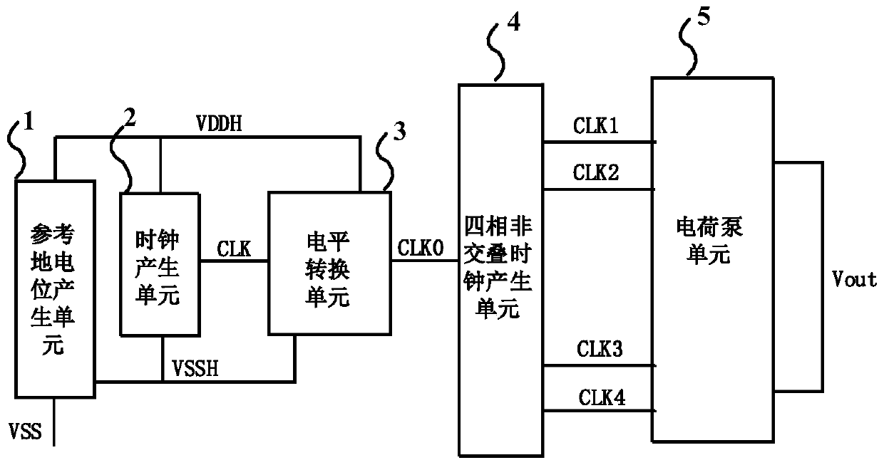
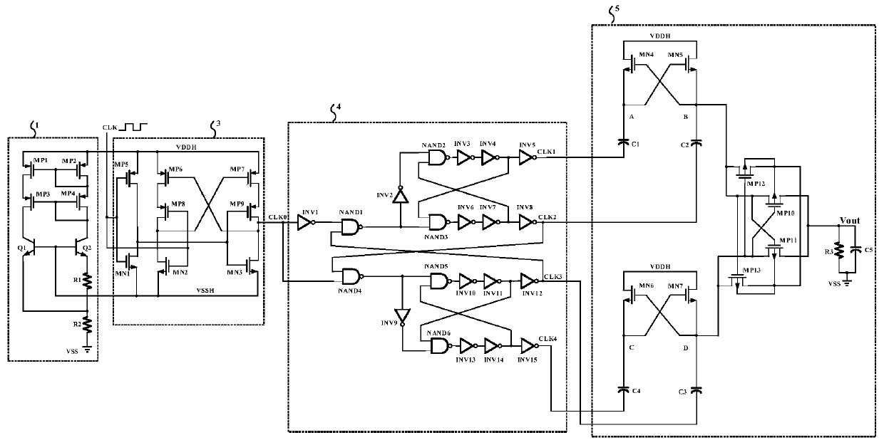
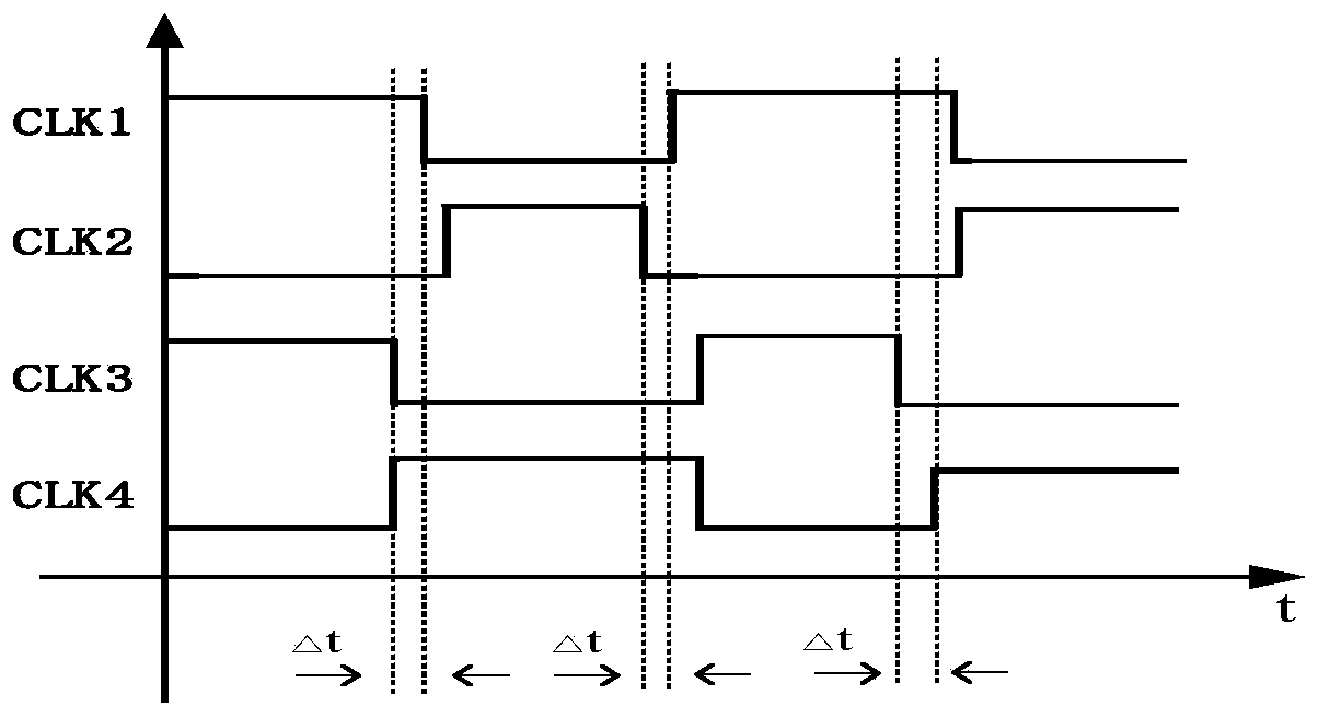
[0046] A charge pump circuit proposed by the present invention is based on multiple non-overlapping clocks and two first-stage charge pumps connected in parallel, using four non-overlapping clock signals to respectively control the two first-stage charge pumps to alternately drive charging and substrate selection The gate and substrate potentials of the switching tubes are controlled by a method, which effectively avoids the occurrence of collusion phenomenon, eliminates the threshold loss caused by the body effect, and improves the charging efficiency of the charge pump. like figure 1 Shown is the overall block diagram of the charge pump structure proposed by the present invention, including a reference ground potential generation unit 1, a level conversion unit 3, a four-phase non-overlapping clock generation unit 4 and a c...


PUM


Abstract

A charge pump circuit based on multiple non-overlapping clocks belongs to the technical field of electronic circuits. The reference ground potential generation unit is used to generate the reference ground potential; the control signal of the level conversion unit is a clock control signal, which is used to generate a clock output signal; the input signal of the four-phase non-overlapping clock generation unit is a clock output signal, which is used to generate The first non-overlapping clock signal, the second non-overlapping clock signal, the third non-overlapping clock signal and the fourth non-overlapping clock signal; the charge pump unit is composed of two first-stage charge pumps connected in parallel, two first-stage charge pumps The first non-overlapping clock signal and the second non-overlapping clock signal, the third non-overlapping clock signal and the fourth non-overlapping clock signal respectively control the alternate drive charging to pump up the power supply voltage of the charge pump unit to generate a charge pump circuit output voltage. The invention avoids the generation of the collusion phenomenon, eliminates the threshold loss caused by the body effect, reduces the ripple, and improves the charging efficiency of the charge pump.

Description

technical field [0001] The invention belongs to the technical field of electronic circuits and relates to a charge pump circuit based on multiple non-overlapping clocks. Background technique [0002] At this stage, with the widespread use of memory, the writing and erasing of data requires an operating voltage much higher than the power supply voltage. Therefore, a charge pump can be used to obtain a high operating voltage through a lower power supply voltage. Multi-stage charge pump There are problems such as efficiency loss and large ripple at each stage, and there is a collusion phenomenon in the traditional cross-coupled charge pump. The collusion phenomenon is the branch circuit leakage phenomenon of the charge pump during the turn-on and turn-off process of the MOS transistor. Contents of the invention [0003] Aiming at the problems of the above-mentioned collusion phenomenon in the traditional cross-coupled charge pump and the efficiency loss and large ripple of ea...

Claims


Application Information

Patent Timeline
Patent Type & Authority Patents(China)
IPC IPC(8): H02M3/07
CPCH02M3/07
Inventor 李泽宏张成发孙河山熊涵风赵念
Owner UNIV OF ELECTRONICS SCI & TECH OF CHINA
Learn More