
Charging and discharging interface, method, charging pile, and electronic device for vehicle-mounted AC charging and discharging machine

A technology of charging and discharging interface and charging and discharging machine, applied in the field of electric vehicles, can solve the problems of inability to communicate, lack of AC discharge process of electric vehicles, etc., to avoid peak power consumption, improve power grid utilization efficiency, and facilitate comprehensive control.

Pending Publication Date: 2018-08-21
WM SMART MOBILITY (SHANGHAI) CO LTD
View PDF7 Cites 10 Cited by
  • Summary
  • Abstract
  • Description
  • Claims
  • Application Information

AI Technical Summary

Problems solved by technology

[0005] Based on this, it is necessary to provide the charging and discharging interface, method, charging pile, and electronic equipment of the vehicle-mounted AC charging and discharging machine in view of the technical problem that the existing technology lacks the AC discharging process of the electric vehicle and cannot communicate.

Method used


Image

  • Charging and discharging interface, method, charging pile, and electronic device for vehicle-mounted AC charging and discharging machine
  • Charging and discharging interface, method, charging pile, and electronic device for vehicle-mounted AC charging and discharging machine
  • Charging and discharging interface, method, charging pile, and electronic device for vehicle-mounted AC charging and discharging machine

Examples


Embodiment Construction

[0071] The present invention will be described in further detail below in conjunction with the accompanying drawings and specific embodiments.

[0072] like Figure 4a Shown is a schematic structural diagram of a charging and discharging interface of a vehicle-mounted AC charging and discharging machine according to the present invention, including: a vehicle-mounted interface body and a vehicle-mounted charging connection confirmation interface (CC) 41a, a vehicle-mounted control confirmation interface (CP) arranged on the vehicle-mounted interface body. ) 42a, vehicle protection earth interface (PE) 43a, vehicle AC power supply interface (L) 44a, vehicle neutral line interface (N) 45a, and vehicle bus communication interface (CANH) 46a, (CANL) 47a, the vehicle charging connection confirmation The insulating layer of the interface 41a is wrapped with a metal connection layer as a vehicle bus communication interface 46a, and the insulation layer of the vehicle control confirma...


PUM


Abstract

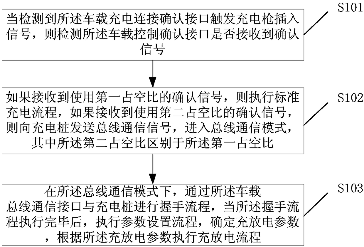
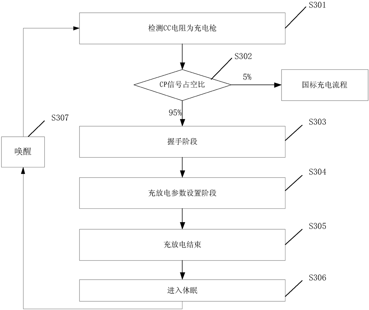
The invention discloses a charging and discharging interface, a method, a charging pile, and an electronic device for a vehicle-mounted AC charging and discharging machine. The charging and discharging method for the vehicle-mounted AC charging and discharging machine comprises the following steps: detecting whether a vehicle-mounted control confirmation interface receives confirmation signals ornot when detecting that a vehicle-mounted charging connection confirmation interface triggers charging gun insertion signals; if receiving confirmation signals using a first duty ratio, performing a standard charging process, and if receiving confirmation signals using a second duty ratio, transmitting a bus communication signal to the charging pile, and entering a bus communication mode, whereinthe second duty ratio (95%) is different from the first duty ratio (5% to 90%); in the bus communication mode, performing a handshake flow, a parameter setting flow and a charging and discharging flowthrough a vehicle-mounted bus communication interface and the charging pile. By modifying the duty ratio of the confirmation signals, a vehicle is guided to be communicated with the charging pile byusing a CAN bus, thereby establishing a more reliable data interaction mode.

Description

technical field [0001] The invention relates to the technical field related to electric vehicles, in particular to a charging and discharging interface of a vehicle-mounted AC charging and discharging machine, a method, a charging pile, and electronic equipment. Background technique [0002] Due to the gradual development of electric vehicles, charging has become a large load on the grid. Due to the limited load of the grid, it will lead to overload of the grid load and stop power supply. Suppose, after 10 years, Chengdu has a population of 10 million, and there are 1 million new energy vehicles equipped with 20kw chargers. If all users charge at the same time at night, it will consume 20 million watts, which is equivalent to the power generation of a Three Gorges Dam. [0003] Therefore, it is an imminent task to avoid charging during peak power consumption in cities, and to be able to export electricity from vehicles during peak power consumption. [0004] However, the e...

Claims


Application Information

Patent Timeline
Patent Type & Authority Applications(China)
IPC IPC(8): B60L11/18
CPCB60L53/00B60L53/60Y02T90/16Y02T10/70Y02T90/12Y02T10/7072Y02T90/14
Inventor 周继云寇芯晨
Owner WM SMART MOBILITY (SHANGHAI) CO LTD
Learn More