Earthwork transportation system used for foundation pit engineering and construction method

A transportation system and foundation pit technology, applied in infrastructure engineering, excavation, construction, etc., can solve the problems of earth lifting, small transfer space, difficult operation of large-scale earth borrowing equipment, huge dust and haze, etc., and achieve the construction progress. Efficient operation, high environmental protection value, and the effect of reducing dust and haze

Inactive Publication Date: 2018-08-21
CHINA CONSTR THIRD ENG BUREAU GRP CO LTD
View PDF5 Cites 2 Cited by
  • Summary
  • Abstract
  • Description
  • Claims
  • Application Information

AI Technical Summary

Problems solved by technology

[0002] With the development of urban construction, high-rise buildings and large public buildings are gradually increasing. However, the excavation of foundation pits in densely built urban areas is restricted by negative factors such as small sites and polluted environment, which brings huge costs and time limit for engineering construction. challenge
Especially for construction projects in urban core areas, such as (semi) cover-excavation construction, due to the limited space, the space for earthwork lifting and transfer is extremely small, and it is difficult for large-scale earthwork equipment to operate, which seriously hinders the construction progress; at the same time, conventional earthwork The huge dust and smog caused by the excavation mode in urban areas also bring new problems to urban environmental protection

Method used


Image

  • Earthwork transportation system used for foundation pit engineering and construction method
  • Earthwork transportation system used for foundation pit engineering and construction method
  • Earthwork transportation system used for foundation pit engineering and construction method

Examples


Embodiment Construction

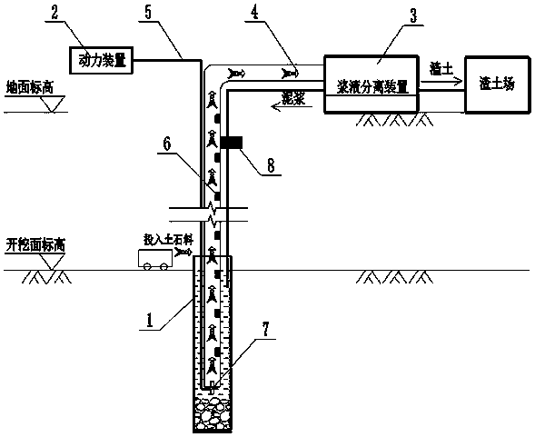
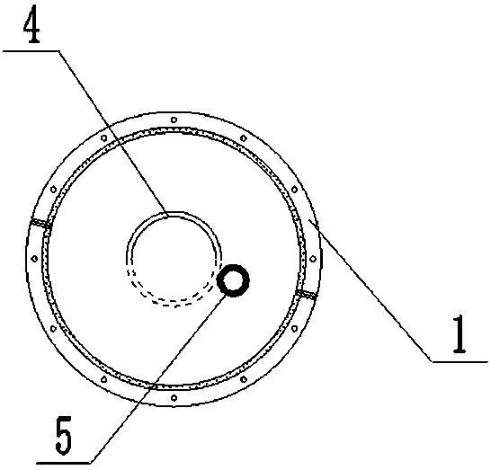
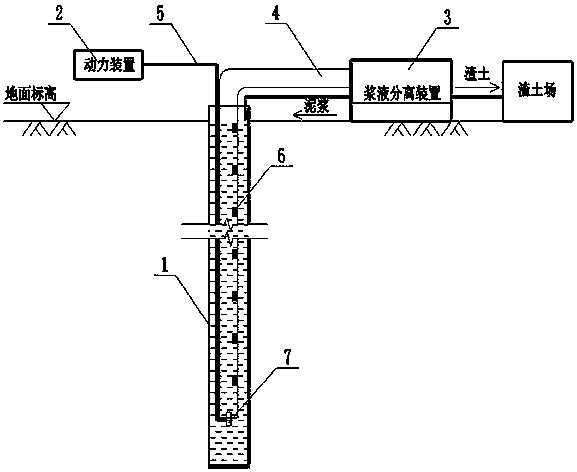
[0029] Such as figure 1 As shown, it is a schematic diagram of the overall structure of an earthwork transportation system used in foundation pit engineering according to the present invention. The system includes a steel casing 1, a power device 2, a slurry separation device 3, a conduit 4, an air pipe 5, and an anti-blocking pipe device 6. Gas-liquid mixer 7 and fixed support structure 8 .

[0030] The steel casing 1 is buried in the soil, and the casing is filled with mud and earthwork mixture to provide a safe and stable operating environment for the entire transportation system, and will be gradually removed later with the excavation of the earthwork.

[0031] The power unit 2 is an air compressor, which is connected with the transportation system through the air pipe 5, and provides the power required for transportation for the whole system.

[0032] The slurry separation device 3 is composed of a slurry pipe, a slurry pump and a slurry separator, which mainly completes...


PUM


Abstract

The invention discloses an earthwork transportation system used for foundation pit engineering and a construction method. The transportation system comprises a steel protective barrel, a power device,a grout separating device, a guide pipe, a gas conveying pipe, a pipe-blocking-preventing device, a gas-liquid mixing device and a fixed supporting structure; the steel protective barrel is embeddedinto soil and is filled with mud and earthwork mixing liquid, the power device is an air compressor, the grout separating device is used for guaranteeing the using performance and circulated utilization of mud, the guide pipe is divided into a vertical part and a horizontal part, the vertical part of the guide pipe is inserted into the steel protective barrel, and the horizontal part of the guidepipe is paved on the ground and fixed; the starting end of the gas conveying pipe is connected with the power device, the vertical part of the guide pipe is inserted into the steel protective barrel in a fixed connection manner, and the tail end is connected with the gas-liquid mixing device; and the pipe-blocking-preventing device prevents the transporting pipe from being blocked. The influencesof surrounding environments on the construction process using the transportation system are small, the occupied construction floor space is small, the earthwork transportation system is suitable for city compact district foundation trench earthwork construction, and pollution to the surrounding environment can be reduced.

Description

technical field [0001] The invention belongs to the technical field of foundation pit construction, and in particular relates to an earthwork transportation system and a construction method for foundation pit engineering. Background technique [0002] With the development of urban construction, high-rise buildings and large public buildings are gradually increasing. However, the excavation of foundation pits in densely built urban areas is restricted by negative factors such as small sites and polluted environment, which brings huge costs and time limit for engineering construction. challenge. Especially for construction projects in urban core areas, such as (semi) cover-excavation construction, due to the limited space, the space for earthwork lifting and transfer is extremely small, and it is difficult for large-scale earthwork equipment to operate, which seriously hinders the construction progress; at the same time, conventional earthwork The huge dust and smog caused by...

Claims


Application Information

Patent Timeline
Patent Type & Authority Applications(China)
IPC IPC(8): E02D15/00E02D17/02
CPCE02D15/00E02D17/02E02D2250/0084
Inventor 余地华周杰刚张晋华惠文军穆冬冬黄晓程雷勇
Owner CHINA CONSTR THIRD ENG BUREAU GRP CO LTD
Why Eureka
Try Eureka