Optical backplane interconnect system

An interconnection system and optical backplane technology, applied in the field of optical backplane interconnection systems, can solve the problems of increasing the number of copper wires, increasing the cost, and complex PCB board structure, and achieving the effect of simplifying the signal transmission channel and improving the electromagnetic compatibility performance.

Active Publication Date: 2018-08-21
FENGHUO COMM SCI & TECH CO LTD
View PDF4 Cites 3 Cited by
  • Summary
  • Abstract
  • Description
  • Claims
  • Application Information

AI Technical Summary

Problems solved by technology

For large-capacity, high-speed communication systems, there are two traditional solutions: one is to increase the number of copper wires, which not only makes the structure of the PCB board complicated, but also increases the cost; the other is to use higher-speed IO or use Differential technology is used to increase the data transmission speed of each copper wire, but due to the inherent characteristics of copper interconnection such as loss and crosstalk, the integrity of high-speed copper interconnection signals is also easily affected

Method used


Image

  • Optical backplane interconnect system
  • Optical backplane interconnect system
  • Optical backplane interconnect system

Examples


Embodiment 1

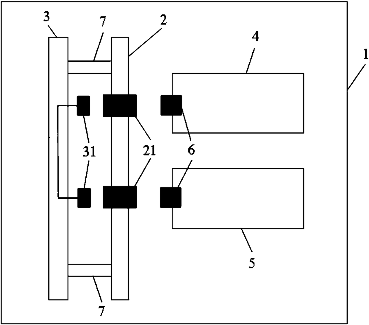
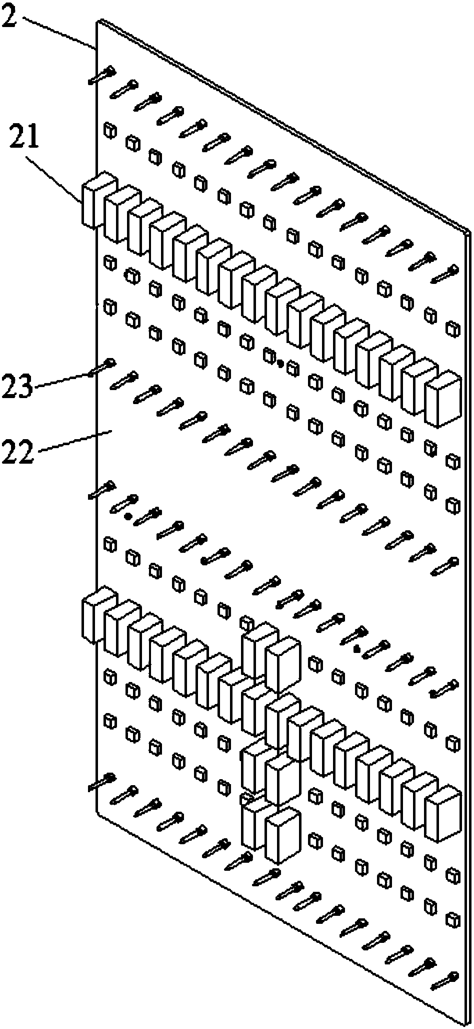
[0038] see Figure 1 to Figure 5 As shown, this embodiment provides an optical backplane interconnection system, which includes a subrack 1 , an electrical backplane 2 , an optical backplane 3 , an optical card 4 and an optical switch card 5 .

[0039] At least one electrical backplane 2 is fixed on the subrack 1 . The subrack 1 is mainly used to provide a supporting structure for the entire optical backplane interconnection system.

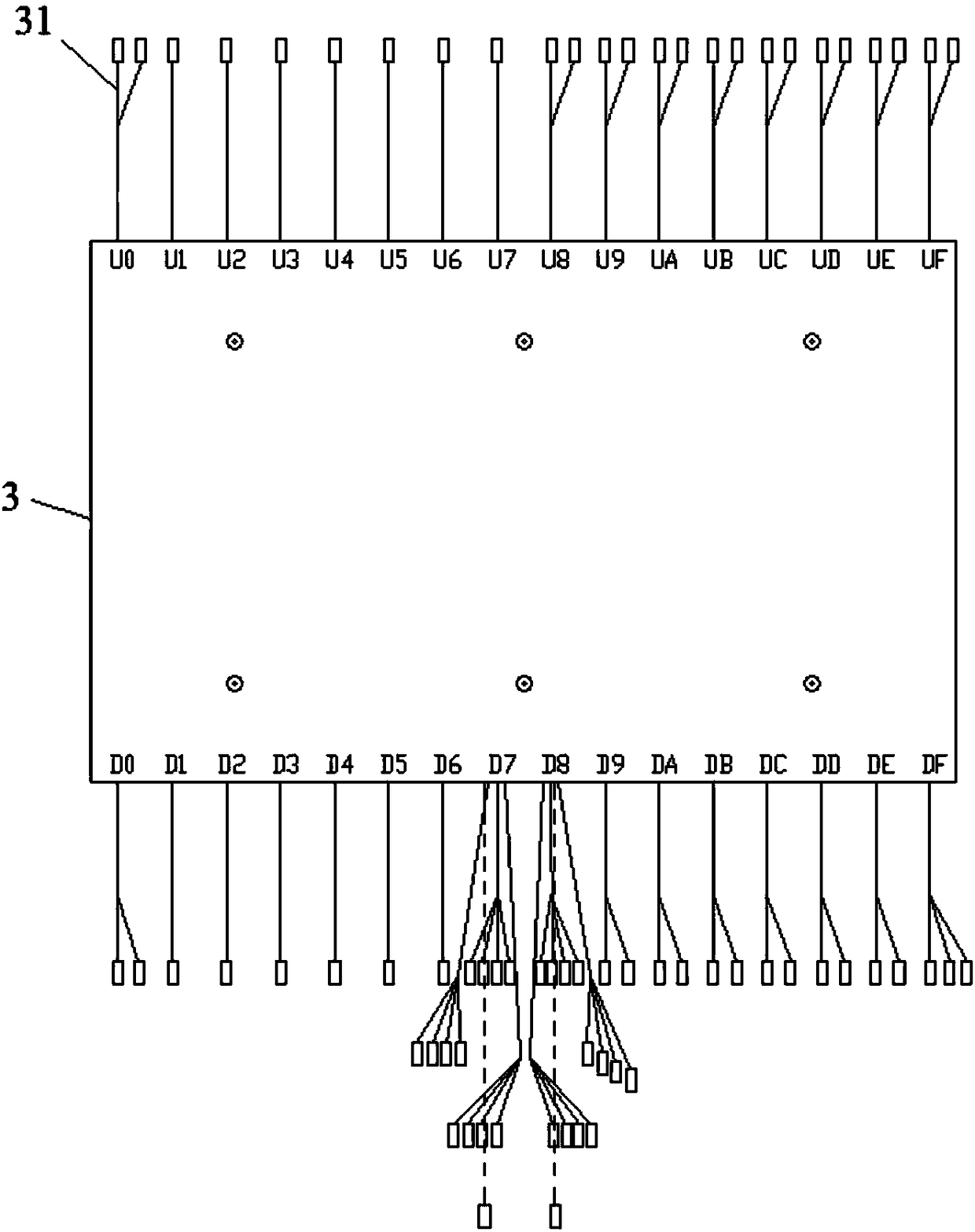
[0040] The optical backplane 3 is fixed on the subrack 1 and on one side of the electric backplane 2 , and optical fibers are arranged in the optical backplane 3 . The optical backplane 3 provides optical fiber routing for the entire optical backplane interconnection system.

[0041] The optical card 4 is fixed on the subrack 1 and located on the side of the electrical backplane 2 away from the optical backplane 3 , and the optical card 4 is connected to the optical backplane 3 through the electrical backplane 2 .

[0042] The optical switch c...

Embodiment 2

[0046] see Figure 1 to Figure 5 As shown, this embodiment provides an optical backplane interconnection system, which includes a subrack 1 , an electrical backplane 2 , an optical backplane 3 , an optical card 4 and an optical switch card 5 .

[0047] At least one electrical backplane 2 is fixed on the subrack 1 .

[0048] The optical backplane 3 is fixed on the subrack 1 and on one side of the electric backplane 2 , and optical fibers are arranged in the optical backplane 3 .

[0049] The optical card 4 is fixed on the subrack 1 and located on the side of the electrical backplane 2 away from the optical backplane 3 , and the optical card 4 is connected to the optical backplane 3 through the electrical backplane 2 .

[0050] The optical switch card 5 is fixed on the subrack 1 and is located on the side of the electric backplane 2 away from the optical backplane 3. The optical switch card 5 is connected to the optical backplane 3 through the electric backplane 2, and the opti...

Embodiment 3

[0058] see Figure 1 to Figure 5 As shown, this embodiment provides an optical backplane interconnection system, which includes a subrack 1 , an electrical backplane 2 , an optical backplane 3 , an optical card 4 and an optical switch card 5 .

[0059] At least one electrical backplane 2 is fixed on the subrack 1 .

[0060] The optical backplane 3 is fixed on the subrack 1 and on one side of the electric backplane 2 , and optical fibers are arranged in the optical backplane 3 .

[0061] The optical card 4 is fixed on the subrack 1 and located on the side of the electrical backplane 2 away from the optical backplane 3 , and the optical card 4 is connected to the optical backplane 3 through the electrical backplane 2 .

[0062] The optical switch card 5 is fixed on the subrack 1 and is located on the side of the electric backplane 2 away from the optical backplane 3. The optical switch card 5 is connected to the optical backplane 3 through the electric backplane 2, and the opti...


PUM


Abstract

The invention discloses an optical backplane interconnection system, and relates to the technical field of communication equipment. The system includes: a sub frame, wherein at least one electrical backplane is fixed on the sub frame; an optical backplane, wherein the optical backplane is fixed on the sub frame and fixed on one side of the electrical backplane. The optical backplane is internallyprovided with an optical fiber; a fiber clamp, wherein the fiber clamp is fixed on the sub frame and is arranged on one side of the electrical backplane, far away from the optical backplane. The fiberclamp is butted with the optical backplane through the electrical backplane; an optical exchange clamp, wherein the optical exchange clamp is fixed on the sub frame and arranged on one side of the electrical backplane, far from the optical backplane. The optical exchange clamp is butted with the optical backplane through the electrical backplane. The optical exchange clamp, the fiber clamp and the optical backplane form an optical path through the electrical backplane. The optical backplane interconnection system is low in cost and low in loss and is not easily to be disturbed.

Description

technical field [0001] The invention relates to the technical field of communication equipment, in particular to an optical backplane interconnection system. Background technique [0002] As a key component of the communication transmission system, the high-speed backplane can be implemented in two forms: electric backplane and optical backplane. [0003] The traditional electrical backplane interconnection is realized by way of copper interconnection. For large-capacity, high-speed communication systems, there are two traditional solutions: one is to increase the number of copper wires, which not only makes the structure of the PCB board complicated, but also increases the cost; the other is to use higher-speed IO or use Differential technology is used to increase the data transmission speed of each copper wire, but due to the inherent characteristics of copper interconnection such as loss and crosstalk, the integrity of high-speed copper interconnection signals is also ea...

Claims


Application Information

Patent Timeline
Patent Type & Authority Applications(China)
IPC IPC(8): G02B6/42G02B6/40
CPCG02B6/40G02B6/4219
Inventor 廖骞邹崇振陈晓峰
Owner FENGHUO COMM SCI & TECH CO LTD
Why Eureka
Try Eureka