Wheel hub permanent magnet synchronous motor

A permanent magnet synchronous motor, wheel hub technology, applied in synchronous motors with static armatures and rotating magnets, magnetic circuits, electric components, etc., can solve problems such as limiting the development of external rotor motors and the inability of external rotor motors to be used directly. Achieve the effect of fast starting speed, strong overload capacity and wide speed regulation range

Pending Publication Date: 2018-08-21
包头天工电机有限公司
View PDF8 Cites 1 Cited by
  • Summary
  • Abstract
  • Description
  • Claims
  • Application Information

AI Technical Summary

Problems solved by technology

[0007] With the development of electric vehicles, the technical advantages of external rotor motors can be reflected in electric vehicles. However, the external rotor motors currently used cannot be directly used in automobiles, which limits the development of external rotor motors.

Method used


Image

  • Wheel hub permanent magnet synchronous motor
  • Wheel hub permanent magnet synchronous motor
  • Wheel hub permanent magnet synchronous motor

Examples


Embodiment Construction

[0029] The following description illustrates specific embodiments of the invention sufficiently to enable those skilled in the art to practice and reproduce it.

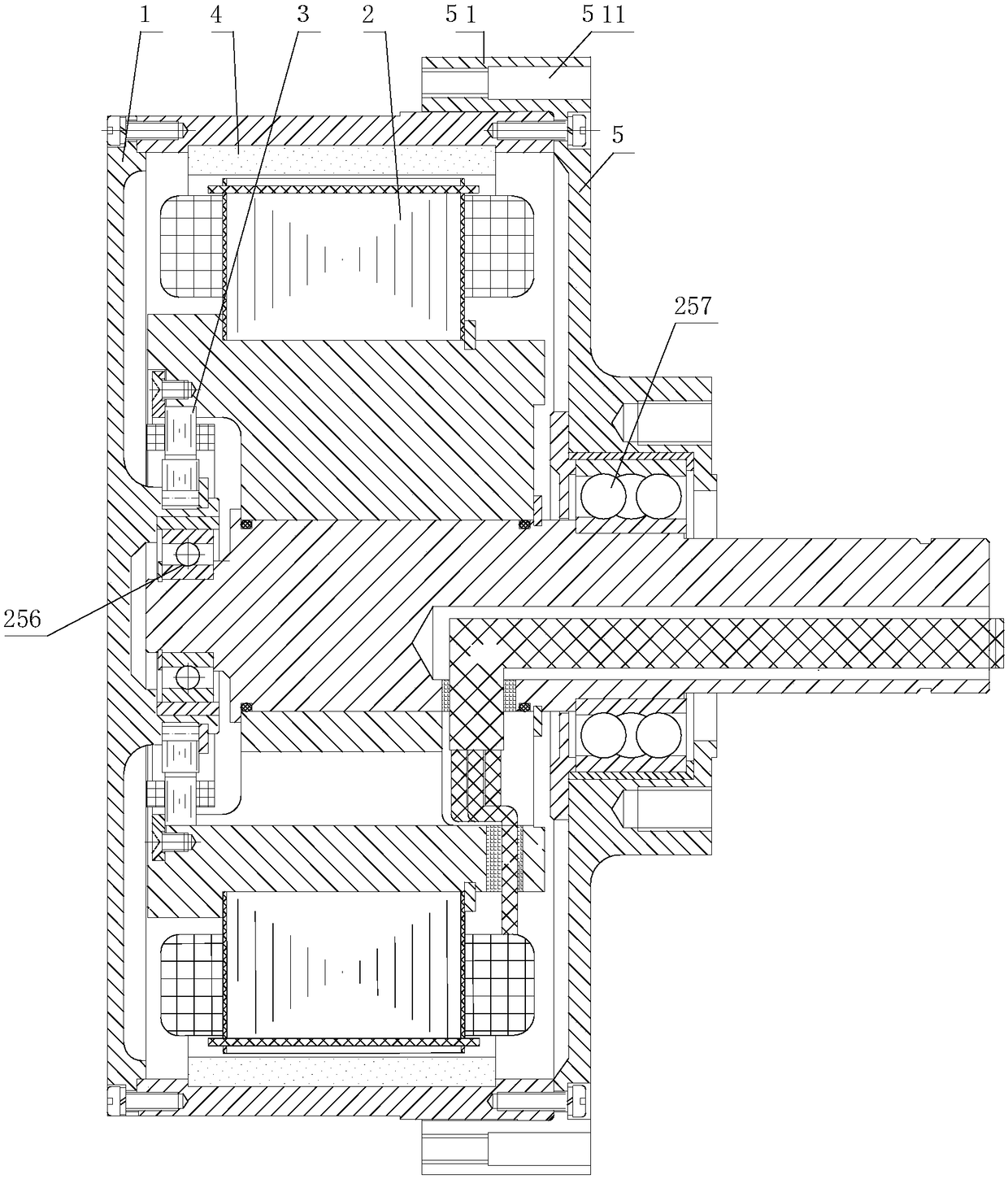
[0030] Such as figure 1 Shown is a schematic structural view of the hub permanent magnet synchronous motor in the present invention.

[0031] The structure of hub permanent magnet synchronous motor includes: front end cover 1, stator 2, rotary transformer 3, permanent magnet rotor 4, rear end cover 5; 2 One end is movably connected to the inner side of the front end cover 1, and the other end protrudes from the shaft hole of the rear end cover 5; the resolver 3 is arranged between the stator 2 and the front end cover 1; the front end cover 1, the permanent magnet rotor 4, and the rear end cover 5 1. The stator 2 is coaxially installed, the front end cover 1, the permanent magnet rotor 4, and the rear end cover 5 rotate, and the stator 2 does not rotate.

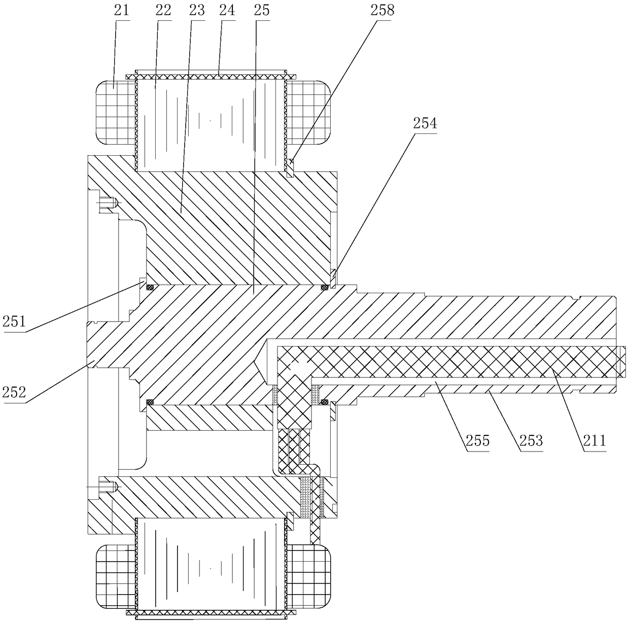
[0032] Such as figure 2 Shown is a schematic structural vi...


PUM


Abstract

The invention discloses a wheel hub permanent magnet synchronous motor. The motor comprises a front end cover, a stator, a rotary transformer, a permanent magnet rotor and a rear end cover; the frontend cover and the rear end cover are installed at the two ends of the permanent magnet rotor respectively, one end of the stator is movably connected to the inner side of the front end cover, the other end of the stator protrudes out from a shaft hole of the rear end cover, and the rotary transformer is fixed to the end of the stator; the front end cover, the permanent magnet rotor, the rear end cover and the stator are coaxially installed. The motor has the advantages of high starting speed, good low-speed performance, high overload capacity, stable high-speed running, wide speed regulation range, wide efficient working area and the like.

Description

technical field [0001] The invention relates to a synchronous motor, in particular to a hub permanent magnet synchronous motor. Background technique [0002] There are currently two types of motors: [0003] 1. A permanent magnet motor with a rotating shaft. [0004] The traditional permanent magnet motor is wound on the stator (frame), and the permanent magnet is combined with the shaft on the rotor to form a permanent magnet rotor. After the stator winding is energized, the stator does not rotate, and the permanent magnet rotor rotates, thereby generating torque, which is output by the rotating shaft torque. [0005] 2. Outer rotor motor. [0006] The shaft of the outer rotor motor does not rotate, and the torque is output through the rotation of the outer rotor. Its structure is exactly the opposite of the traditional motor structure above, that is, the winding of the motor is on the inner stator, and the permanent magnet is on the outer rotor (on the frame). After th...

Claims


Application Information

Patent Timeline
Patent Type & Authority Applications(China)
IPC IPC(8): H02K21/22H02K29/12H02K1/27
CPCH02K1/2786H02K21/22H02K29/12
Inventor 宫国强乔振宁武春久滕裕国兰卫中刘永明
Owner 包头天工电机有限公司
Why Eureka
Try Eureka