Auto spare parts cleaning device

A technology for cleaning devices and auto parts, which is applied in the directions of drying gas arrangement, cleaning method and utensils, and cleaning methods using liquids, etc., which can solve the problems of low cleaning efficiency, reduced cleaning efficiency, and low efficiency, so as to improve drying efficiency and improve The effect of cleaning efficiency

Inactive Publication Date: 2018-08-24
NINGBO HAIMAN AUTOMOTIVE TECH CO LTD
View PDF10 Cites 6 Cited by
  • Summary
  • Abstract
  • Description
  • Claims
  • Application Information

AI Technical Summary

Problems solved by technology

[0004] The above scheme uses the water spray main pipe and the side spray pipe to wash the accessories in all directions, which solves the problem of low efficiency in the traditional cleaning process; but the above scheme still has the following problems: the above scheme clamps and fixes the accessories through the rotating arm structure Finally, the 360-degree rotation with the water spray main pipe and the side spray pipe to clean the accessories in all directions can further improve the cleaning effect and improve the cleaning efficiency, but the position where the accessories are in contact with the rotating arm structure will hardly be in contact with water. After the other parts of the accessories are cleaned, the cleaned parts of the accessories need to be clamped by the rotating arm structure for secondary cleaning. The cleaning efficiency is still low. On the other hand, after the accessories are cleaned, the operator needs to remove the accessories from the The swivel arm structure is taken out, further reducing the cleaning efficiency

Method used


Image

  • Auto spare parts cleaning device

Examples


Embodiment Construction

[0016] Further detailed explanation through specific implementation mode below:

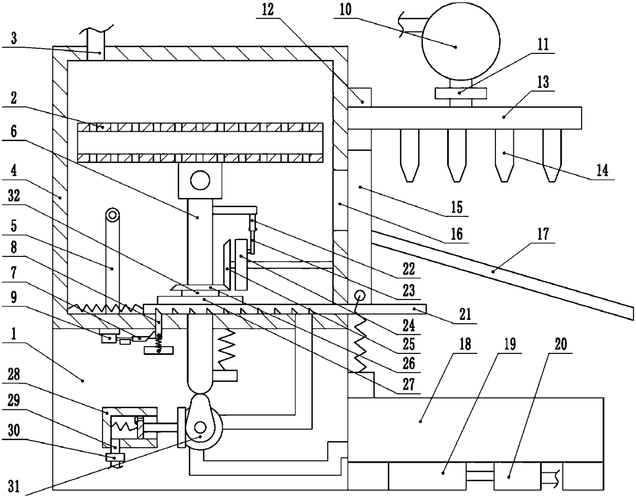
[0017] The reference signs in the drawings of the description include: frame 1, storage box 2, water inlet pipe 3, cleaning box 4, ejector rod 5, slide rod 6, second wedge rod 7, first wedge rod 8, cylinder 9, air bag 10. Second valve 11, electromagnet 12, jet pipe 13, jet head 14, sealing plate 15, outlet 16, feeding plate 17, water tank 18, filter 19, water pump 20, rack 21, connecting rod 22 , crank 23, turntable 24, first bevel gear 25, second bevel gear 26, sector gear 27, air pump 28, air pipe 29, one-way valve 30, cam 31, sleeve 32.

[0018] The embodiment is basically as attached figure 1Shown: Auto parts cleaning device, including a frame 1 and a cleaning box 4, the cleaning box 4 is fixed on the frame 1 by bolts, the top of the cleaning box 4 is connected with a water inlet pipe 3, and the bottom of the cleaning box 4 is connected with a water outlet pipe, the frame 1 is fixed with a ...


PUM


Abstract

The invention relates to an auto spare parts cleaning device which comprises a rack and a cleaning tank. The cleaning tank communicates with a water inlet pipe and a water outlet pipe; a turbine is rotatably connected into the water outlet pipe; a cam and the turbine are coaxially connected; a sliding rod is slidably connected into the cleaning tank; the cam is abutted against the sliding rod; a placement tank is hinged to the top part of the sliding rod; a discharge hole is formed in one side of the cleaning tank; an ejector rod is fixedly connected onto the cleaning tank; a rotary plate is rotatably connected into the cleaning tank; a crank is hinged onto an eccentric center of the rotary plate, and is hinged with a connecting rod; the connecting rod is fixedly connected with the slidingrod; the rotary plate is coaxially connected with a first bevel gear; the first bevel gear meshes with a second bevel gear; the second bevel gear is coaxially connected with a fan gear; the fan gearmeshes with a rack; a plurality of wedge slots are formed in the rack; a first wedge rod is slidably connected into the cleaning tank; a seal plate is slidably connected to the discharge hole of the cleaning tank; and the rack is abutted against the seal plate. Compared with the prior art, according to the scheme, spare parts are placed into the placement tank, so that the cleaning efficiency is greatly improved.

Description

technical field [0001] The invention relates to the field of accessory cleaning equipment, in particular to an auto accessory cleaning device. Background technique [0002] At present, after the processing of some auto parts is completed, oil stains often adhere to the outer surface and inner cavity surface of the auto parts, and residual sand and other sundries are usually attached to the inner cavity surface of the auto parts. Cleaning is required to avoid residual sand, oil and other pollutants affecting the quality of auto parts. In the traditional auto parts cleaning process, manual cleaning is usually used to clean the residual sand, oil and other sundries on the surface of auto parts; ensure. [0003] In order to solve the above problems, the utility model patent with the Chinese patent application No. 201620603271.0 discloses a new type of multifunctional auto parts cleaning device including a housing, a water spray main pipe, a spray head, a placement plate, a sid...

Claims


Application Information

Patent Timeline
Patent Type & Authority Applications(China)
IPC IPC(8): B08B3/10B08B3/14F26B21/00
CPCB08B3/044B08B3/14F26B21/00
Inventor 卢文斌
Owner NINGBO HAIMAN AUTOMOTIVE TECH CO LTD
Why Eureka
Try Eureka