Quick knife falling device

A tool drop and fast technology, applied in the direction of auxiliary devices, accessories of toolholders, turning equipment, etc., to achieve the effect of sensitive and fast response, simple action, simple and accurate operation

Active Publication Date: 2018-08-24
SHANGHAI UNIV OF ENG SCI
View PDF11 Cites 5 Cited by
  • Summary
  • Abstract
  • Description
  • Claims
  • Application Information

AI Technical Summary

Problems solved by technology

Fixtures for holding tools

Method used


Image

  • Quick knife falling device
  • Quick knife falling device
  • Quick knife falling device

Examples


Embodiment

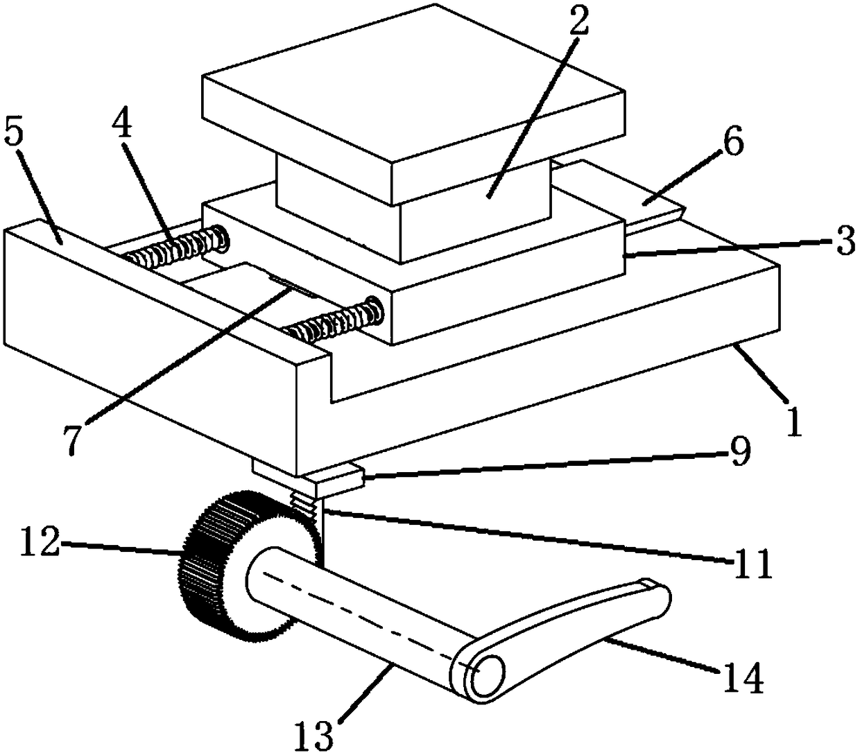
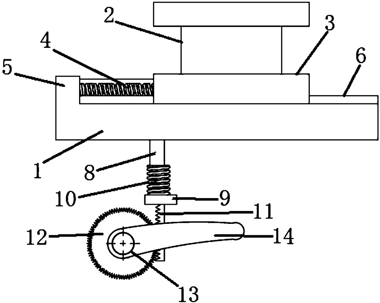
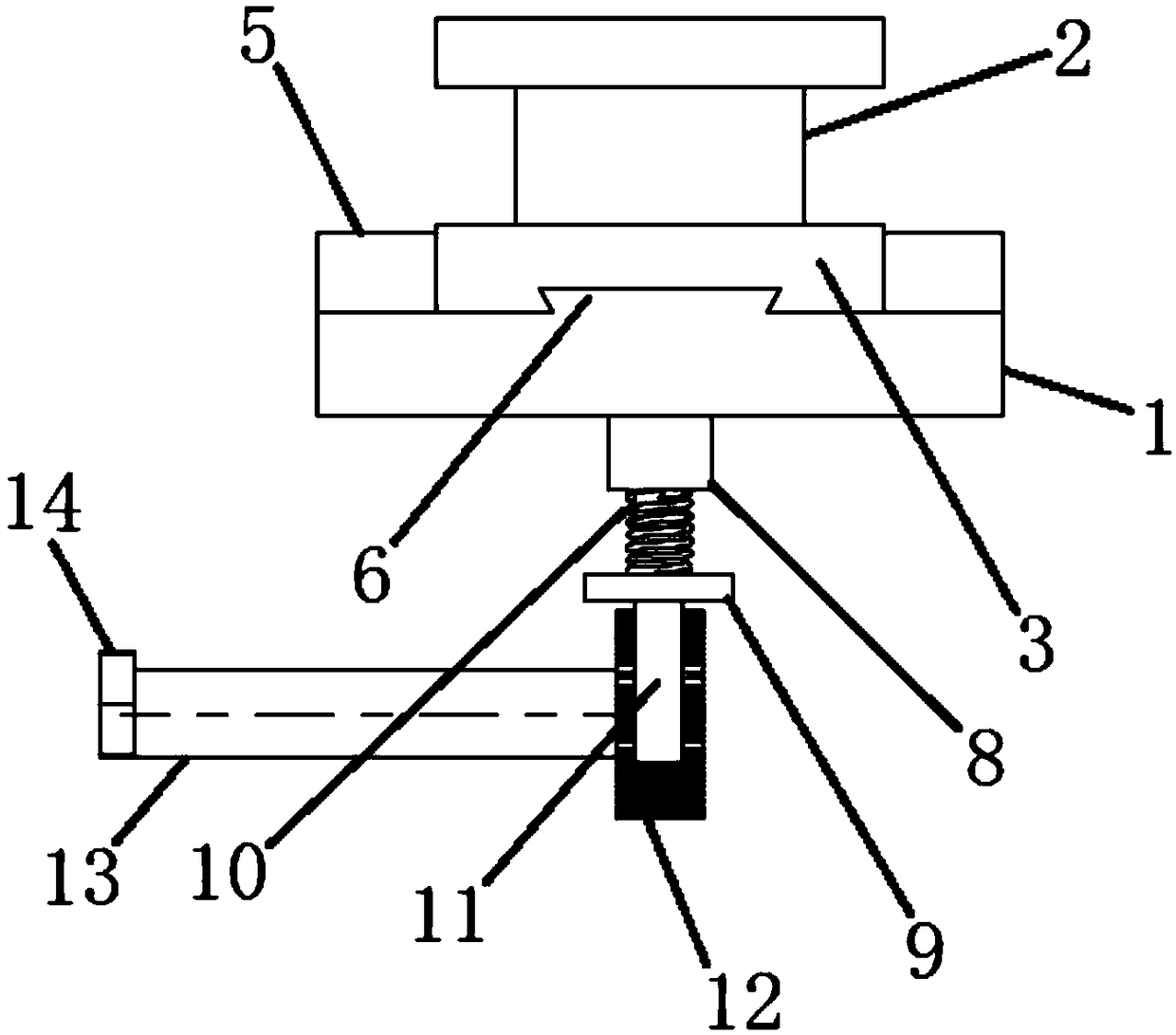
[0031] Such as figure 1 , figure 2 , image 3 A rapid knife drop device is shown, which includes a base 1, a spring push knife drop mechanism slidably arranged on the base 1, and a knife drop control mechanism arranged at the bottom of the base 1 and matched with the spring push knife drop mechanism, A clamp 2 is arranged on the spring pushing and falling knife mechanism.

[0032] Wherein, the spring pushing and dropping mechanism includes a slider 3 slidably arranged on the base 1 and a pressure spring 4 arranged between one end of the slider 3 and the base 1 , and the clamp 2 is arranged on the slider 3 . The base 1 is provided with a pressure spring mounting block 5 , one end of the pressure spring 4 is fixedly connected with the pressure spring mounting block 5 , and the other end is fixedly connected with the slider 3 . A pair of pressure springs 4 are juxtaposed between the pressure spring mounting block 5 and the slider 3 . The base 1 is provided with a guide block...


PUM


Abstract

The invention relates to a quick knife falling device. The quick knife falling device comprises a pedestal, a spring-pushed knife falling mechanism and a knife falling control mechanism, wherein the spring-pushed knife falling mechanism is slidably arranged on the pedestal; the knife falling control mechanism is arranged at the bottom of the pedestal and is matched with the spring-pushed knife falling mechanism; and the spring-pushed knife falling mechanism is provided with a clamp. Compared with the prior art, in the quick knife falling device provided by the invention, a pressure spring canbe used for driving a slider to move quickly so as to realize quick falling of a knife; the overall knife falling action is simple; the work stability is good; adverse effects to a lathe are prevented; the quick knife falling device is safe and reliable; quick knife falling and restoration of the slider can be realized by virtue of the knife falling control mechanism; the response is sensitive andquick; and the operation is simple and accurate.

Description

technical field [0001] The invention belongs to the technical field of lathe processing, and relates to a rapid tool drop device. Background technique [0002] When performing lathe cutting, it is often necessary to measure the influence of a certain type of tool on the curling angle of the chip. The commonly used measurement method is to retract the tool first, then stop the machine tool, and measure the angle. However, because the angle that needs to be measured is transient, Therefore, this method is prone to large deviations from the experimental results. [0003] In order to study the cutting mechanism of the metal cutting process, some enterprises use a rapid tool drop device to obtain the deformation zone and chip root samples under the cutting conditions through the sudden tool drop during the cutting process, and then use different methods to observe them. Establish various physical models of chip formation to reveal the metal cutting mechanism and achieve the purp...

Claims


Application Information

Patent Timeline
Patent Type & Authority Applications(China)
IPC IPC(8): B23B25/00B23Q17/00
CPCB23B25/00B23Q17/00
Inventor 王鹏王大中姜浪浪刘鑫林靖朋魏磊
Owner SHANGHAI UNIV OF ENG SCI
Why Eureka
Try Eureka