Machining process of loading and unloading conveying device and step shaft sleeves of centerless grinding machine

A technology of centerless grinding machine and transmission device, which is applied in the direction of grinding machines, metal processing equipment, and machine tools designed for grinding the rotating surface of workpieces, etc. It can solve the problems of reducing production efficiency, affecting labor costs, and affecting the quality of finished products, so as to reduce labor intensity. , Increase grinding efficiency and save processing time

Active Publication Date: 2018-08-24
CHONGQING ELECTROMECHANICAL VOCATIONAL INST
View PDF6 Cites 13 Cited by
  • Summary
  • Abstract
  • Description
  • Claims
  • Application Information

AI Technical Summary

Problems solved by technology

[0004] A high-precision stepped bushing part used in automobiles is processed by centerless grinding. When using the existing centerless grinding machine for processing, the worker manually positions the position of the adjustment wheel each time, and manually moves up and down the stepped bushing. The machining accuracy of the stepped bushing is high, and the speed is slow when the adjustment wheel is moved each time. It takes a long time to complete the positioning, grinding an

Method used


Image

  • Machining process of loading and unloading conveying device and step shaft sleeves of centerless grinding machine
  • Machining process of loading and unloading conveying device and step shaft sleeves of centerless grinding machine
  • Machining process of loading and unloading conveying device and step shaft sleeves of centerless grinding machine

Examples


Embodiment Construction

[0034] In order to enable those skilled in the art to understand better, the technical solution of the present invention will be further described below in conjunction with the accompanying drawings and embodiments:

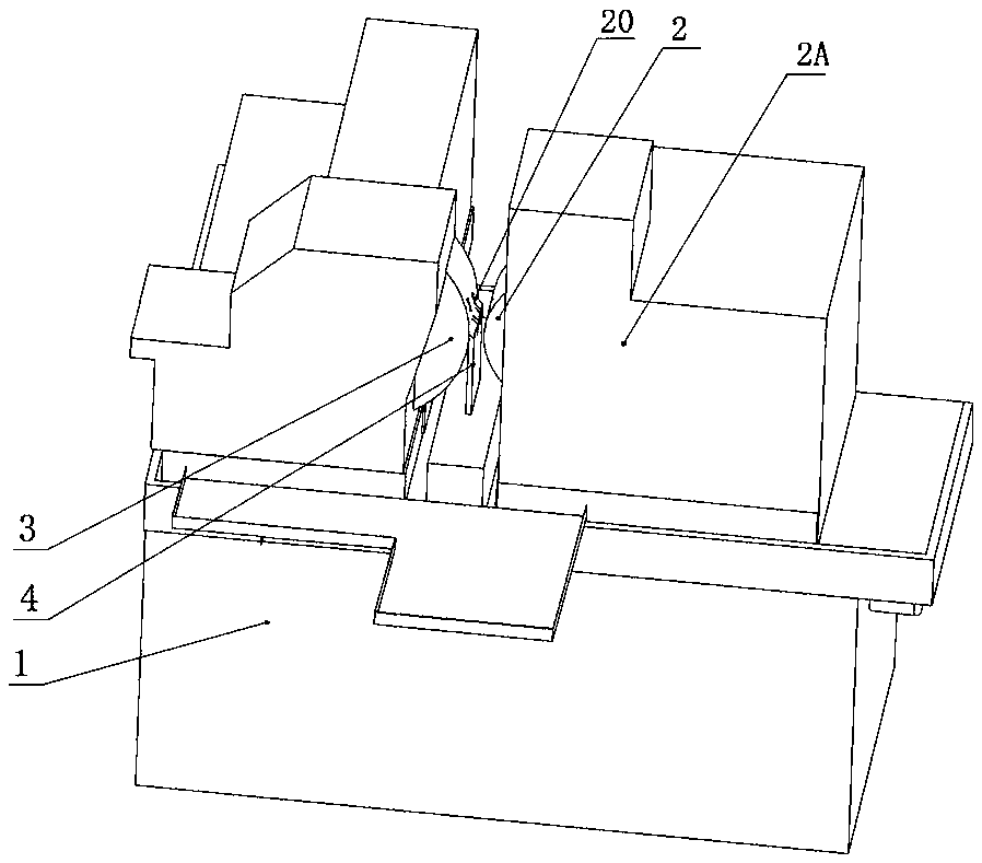
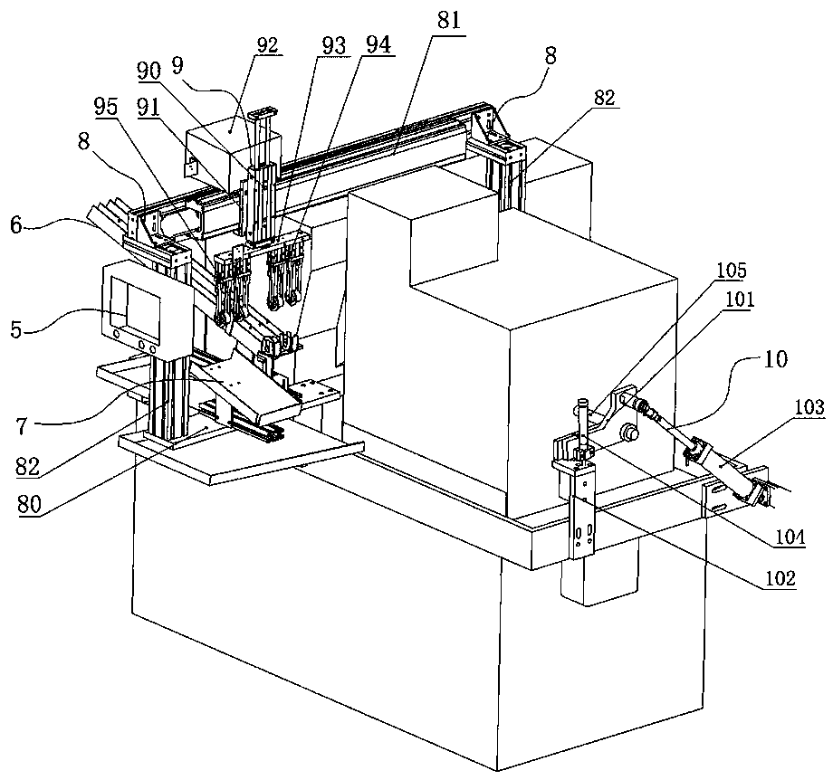
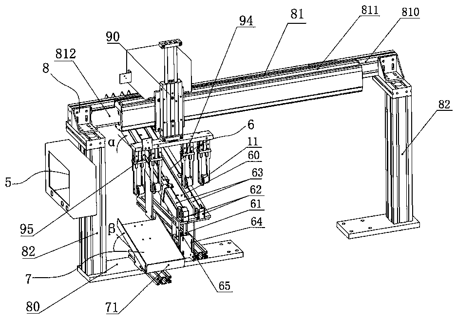
[0035] like figure 1 , figure 2 , image 3 , Figure 4The loading and unloading transmission device of the centerless grinding machine shown, wherein the centerless grinding machine includes a grinding machine seat 1, a grinding wheel 2, an adjustment wheel 3 and a workpiece support 4, and the loading and unloading transmission device includes a control cabinet 5, a feeding mechanism 6, and a feeding bin 7 , loading and unloading conveying mechanism 8, loading and unloading clamping mechanism 9 and propulsion device 10; Described loading and unloading conveying mechanism 8 comprises the base 80 that is placed on the grinding machine seat 1, slide guide rail part 81 and two Y-axis support seats 82, two A Y-axis support seat 82 is placed on the front and rear s...


PUM


Abstract

The invention relates to the field of machining of centerless grinding machines, in particular to a machining process of a loading and unloading conveying device and step shaft sleeves of a centerlessgrinding machine. The centerless grinding machine comprises a grinding machine base, a grinding wheel, an adjusting wheel and a workpiece bracket; the loading and unloading conveying device comprisesa control cabinet, a feeding mechanism, a discharge bin, a loading and unloading conveying mechanism, a loading and unloading clamping mechanism and a pushing device; the control cabinet is electrically connected with the feeding mechanism, the loading and unloading conveying mechanism and the loading and unloading clamping mechanism; the feeding mechanism takes the charge of tidily placing the step shaft sleeves in sequence; the loading and unloading conveying device is an operating procedure of supporting the loading and unloading clamping mechanism, so that the step shaft sleeves are smoothly loaded and unloaded on the grinding machine, and the manual loading time is saved; through cooperation of the pushing device and the discharge bin, full-automatic grinding is realized, so that thelabor intensity of operators is effectively reduced; and a loading clamping hand and an unloading clamping hand can once clamp at least two step shaft sleeves, so that one half of the machining timeis saved, the labor productivity is improved, and the batch production is achieved.

Description

technical field [0001] The invention relates to the mechanical processing field of a centerless grinder, in particular to a processing technology for a loading and unloading transmission device of a centerless grinder and a stepped shaft sleeve. Background technique [0002] The centerless grinding machine is composed of three mechanisms: grinding wheel, adjusting wheel and workpiece support (bracket). The grinding wheel is actually responsible for the grinding work. The adjusting wheel controls the rotation of the workpiece and makes the feed speed of the workpiece occur. As for the workpiece The stand supports the workpiece while grinding. [0003] The centerless grinding wheel is a grinding wheel installed on a centerless grinding machine. It interacts with the guide wheel and the supporting plate to form a grinding method. The workpiece to be processed is supported by the supporting plate and moves from the guiding wheel to the supporting plate. When the circular motion...

Claims


Application Information

Patent Timeline
IPC IPC(8): B24B5/35B24B5/22B24B5/307B24B1/00
CPCB24B1/00B24B5/22B24B5/307B24B5/35B24B5/355Y02P70/10
Inventor 张华杨川张利国尹捷陈华薛锋余衡罗文郑皓匀巩方欣熊茂灰
Owner CHONGQING ELECTROMECHANICAL VOCATIONAL INST
Why Eureka
Try Eureka