
Fixing clamp used for log cutting

A technology for fixing fixtures and logs, used in wood processing appliances, sawing components, manufacturing tools, etc., can solve the problems of single cutting method, low labor productivity, and low profitability.

Inactive Publication Date: 2018-08-24
成都亚工电子科技有限公司
View PDF0 Cites 1 Cited by
  • Summary
  • Abstract
  • Description
  • Claims
  • Application Information

AI Technical Summary

Problems solved by technology

[0002] With the sharp increase in timber demand, the development trend of my country's timber enterprises is better, and the number of timber enterprises above the designated size is also increasing. Some well-known enterprises have mastered the world's most advanced production technology and technology, basically meeting the needs of the market. And has a certain influence in the world, but it is undeniable that the development of China's timber industry with small and medium-sized enterprises as the main body is not balanced. Most small and micro enterprises lack core technology, have not realized brand management, low concentration, and risk resistance The capacity is poor, the labor productivity is not high, and the profitability is not strong. In order to make the enterprise more competitive, my country's wood processing enterprises should actively develop production technology and improve production efficiency. At present, in the process of wood processing, logs are It needs to be cut to continue processing, but the existing cutting methods cannot fix larger trees, the fixing is not stable, and the cutting method is single. It cannot be cut into long strips or inclined cylinders with one machine, which is inconvenient for subsequent processing and low processing efficiency. , can no longer meet the needs of the market

Method used

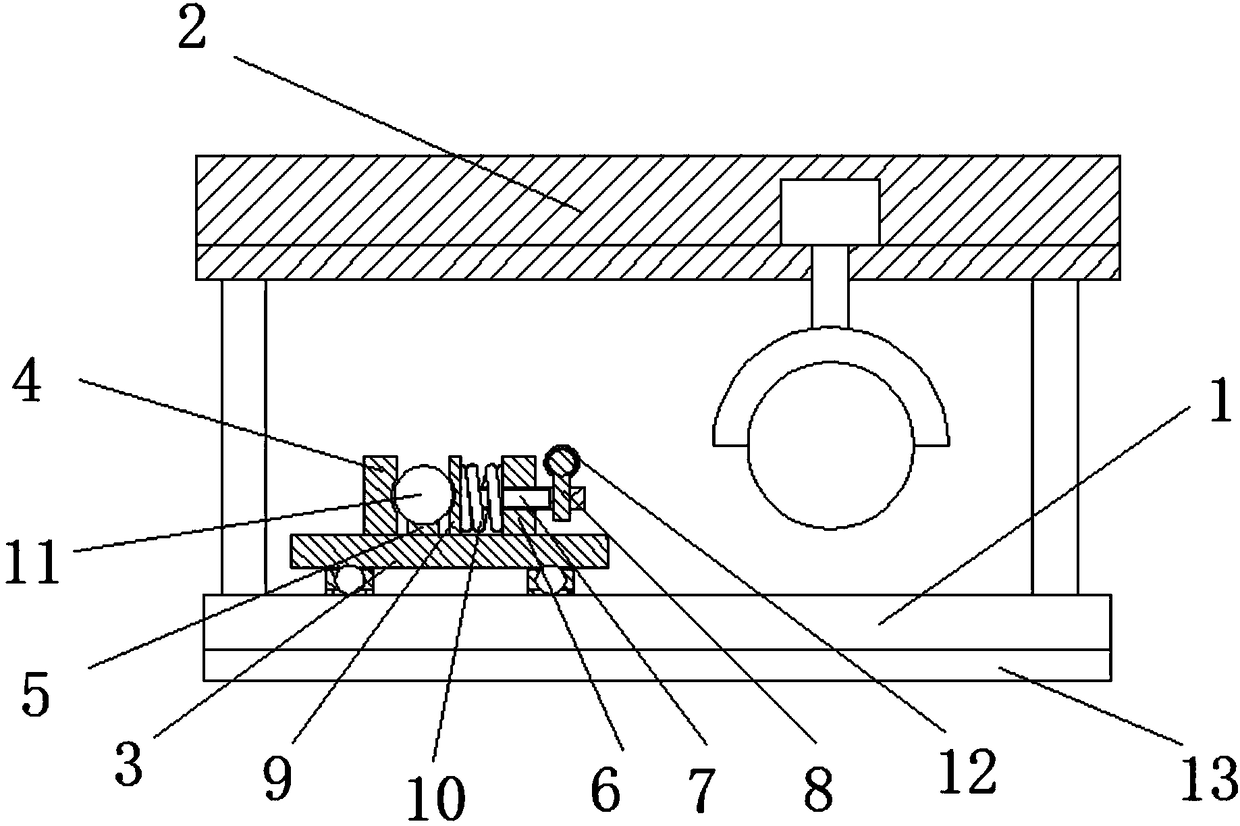

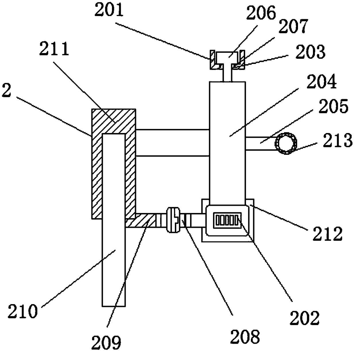
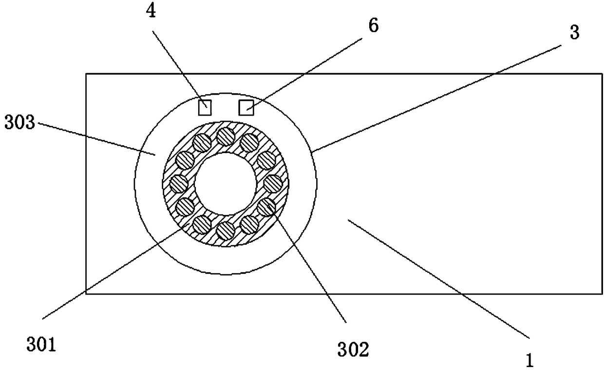
Image

  • Fixing clamp used for log cutting
  • Fixing clamp used for log cutting
  • Fixing clamp used for log cutting

Examples


Embodiment Construction

[0016] The following will clearly and completely describe the technical solutions in the embodiments of the present invention with reference to the accompanying drawings in the embodiments of the present invention. Obviously, the described embodiments are only some, not all, embodiments of the present invention. Based on the embodiments of the present invention, all other embodiments obtained by persons of ordinary skill in the art without making creative efforts belong to the protection scope of the present invention.

[0017] see Figure 1-3 , the present invention provides a technical solution: a fixed fixture for log cutting, including a workbench 1, a cutting device 2 is fixedly installed on the upper surface of the workbench 1, and a rotating Device 3, the rotating device 3 includes an isolation frame 301, the lower surface of the isolation frame 301 is fixedly installed on the upper surface of the left end of the workbench 1, the inside of the isolation frame 301 is pro...


PUM


Abstract

The invention discloses a fixing clamp used for log cutting. The fixing clamp comprises a workbench. Cutting devices are fixedly mounted on the left side and the right side of the upper surface of theworkbench. A rotating device is fixedly mounted on the upper surface of the left end of the workbench. The rotating device comprises an isolation frame. The lower surface of the isolation frame is fixedly mounted on the upper surface of the left end of the workbench. Steel balls are arranged in the isolation frame, and the number of the steel balls is at least 12. The top ends of the steel ballsare slidably connected with a disc. According to the fixing clamp used for log cutting, through the cooperation of the cutting devices, the rotating device and a stud, the problems that according to an existing cutting method, large trees cannot be fixed, fixation is instable, only one cutting mode is available, log cannot be cut into long strips or oblique columns by one machine, subsequent processing is inconvenient, processing efficiency is low, and market requirements cannot be met are solved.

Description

technical field [0001] The invention relates to the technical field of log cutting machinery, in particular to a fixed fixture for log cutting. Background technique [0002] With the sharp increase in timber demand, the development trend of my country's timber enterprises is better, and the number of timber enterprises above the designated size is also increasing. Some well-known enterprises have mastered the world's most advanced production technology and technology, basically meeting the needs of the market. And has a certain influence in the world, but it is undeniable that the development of China's timber industry with small and medium-sized enterprises as the main body is not balanced. Most small and micro enterprises lack core technology, have not realized brand management, low concentration, and risk resistance The capacity is poor, the labor productivity is not high, and the profitability is not strong. In order to make the enterprise more competitive, my country's wo...

Claims


Application Information

Patent Timeline
Patent Type & Authority Applications(China)
IPC IPC(8): B27B29/00B27B5/18B27B5/29
CPCB27B29/00B27B5/18B27B5/29
Inventor 莫亚政
Owner 成都亚工电子科技有限公司
Learn More