Accurately-spraying intelligent plant protection unmanned aerial vehicle with adjusting function
What is Al technical title?
Al technical title is built by PatSnap Al team. It summarizes the technical point description of the patent document.
A plant protection drone, intelligent technology, applied in the field of drones, can solve problems such as distortion, reduce spraying effect, and not enough to kill pests, achieve precise control of pesticide dosage, ensure moving distance, and accurately spray pesticides. Effect
Inactive Publication Date: 2018-08-24
SHENZHEN ANSIKE ELECTRONICS TECH CO LTD
View PDF5 Cites 14 Cited by
Summary
Abstract
Description
Claims
Application Information
AI Technical Summary
This helps you quickly interpret patents by identifying the three key elements:
Problems solved by technology
Method used
Benefits of technology
Problems solved by technology
[0003] In the existing plant protection drones, the drones fly above the crops to spray pesticides on the crops, which not only saves labor costs, but also has faster and more efficient spraying of pesticides than human spraying. , but when the drone is flying, the wind generated by the rotation of the rotor will distort and deform the leaves of the crops. Therefore, when the drone flies away, the crops will bounce back the droplets deposited on the crops in order to restore their original state. As a result, the droplet attachment rate is reduced, the pesticide cannot stay on the leaves of the crops accurately, and the spraying effect is reduced. Not only that, the existing plant protection drones usually spray pesticides evenly above the crops, but due to the crops everywhere The growth and the amount of agricultural pests are different. When the amount of pesticide is too much, it will affect the growth of crops. The practicality of plant protection drones
Method used
Image
Click on the blue label to locate the original text in one second.
Reading with bidirectional positioning of images and text.
Examples
Embodiment Construction
[0026] The present invention is described in further detail now in conjunction with accompanying drawing. These drawings are all simplified schematic diagrams, which only illustrate the basic structure of the present invention in a schematic manner, so they only show the configurations related to the present invention.
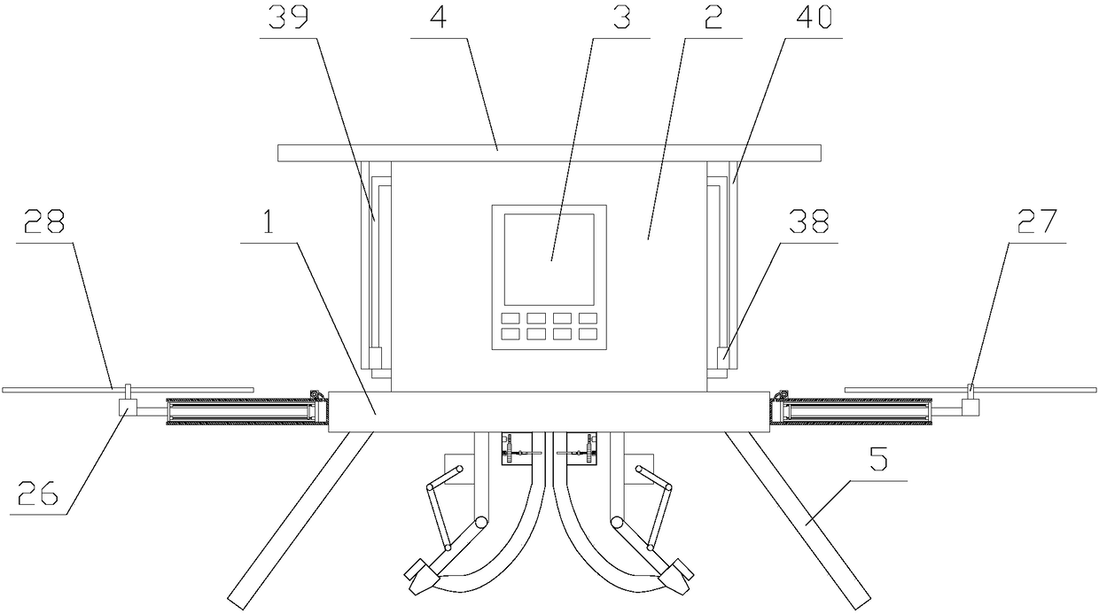
[0027] Such as figure 1 As shown, an intelligent plant protection UAV with adjustment function and precise spraying includes a main body 1, a pesticide box 2, a controller 3, a top plate 4, two installation mechanisms, two spraying mechanisms, several flight mechanisms and several Leg 5, the pesticide box 2 is fixed on the top of the main body 1, the controller 3 is fixed on the pesticide box 2, the main body 1 is provided with a PLC, and the two installation mechanisms are respectively located on both sides of the pesticide box 2, so The top plate 4 is arranged on the top of the pesticide box 2 through the installation mechanism, the flying mechanism is even...
PUM
Abstract
The invention relates to an accurately-spraying intelligent plant protection unmanned aerial vehicle with an adjusting function. The unmanned aerial vehicle comprises a main body, a pesticide tank, atop board, two pesticide spaying mechanisms, multiple flight mechanisms and multiple supporting feet. Each flight mechanism comprises a flight component, an air pump, an air cylinder, a piston board and a telescopic component. Each telescopic component comprises a horizontal motion board, a horizontal motion rod and two horizontal motion units. Each pesticide spraying mechanism comprises a nozzle,a direction adjusting component, a liquid conveying component and a connecting pipe. Each adjusting component is arranged in a corresponding adjusting room. Each adjusting component comprises a firstmotor, a first gear, a second gear, a lead screw, a casing pipe and an adjusting board. By the adoption of the accurately-spraying intelligent plant protection unmanned aerial vehicle with the adjusting function, through the air pumps and the telescopic components in the flight mechanisms, the flight components are away from the main body, crops affected by airflow generated by rotors is avoided,pesticide is sprayed more accurately, furthermore, in the pesticide spaying mechanisms, the spraying amount of the pesticide is flexibly adjusted according to the pest amount around the crops, it isguaranteed that the crops grow healthily, and the practicability of equipment is improved.
Description
technical field [0001] The invention relates to the field of unmanned aerial vehicles, in particular to an intelligent plant protection unmanned aerial vehicle with an adjustment function and precise spraying. Background technique [0002] Unmanned aerial vehicle, unmanned aerial vehicle (UAV) for short, is a new concept weapon equipment in rapid development, which has the advantages of flexible maneuvering, quick response, unmanned flight, and low operation requirements. UAVs equipped with multiple types of sensors can realize real-time image transmission and detection of high-risk areas, which is a powerful supplement to satellite remote sensing and traditional aerial remote sensing. At present, the scope of use of UAVs has been expanded to the three major fields of military, scientific research, and civilian use, specifically in power, communications, meteorology, agriculture, ocean, exploration, photography, disaster prevention and reduction, crop production estimation, ...
Claims
Application Information
Patent Timeline
Application Date:The date an application was filed.
Publication Date:The date a patent or application was officially published.
First Publication Date:The earliest publication date of a patent with the same application number.
Issue Date:Publication date of the patent grant document.
PCT Entry Date:The Entry date of PCT National Phase.
Estimated Expiry Date:The statutory expiry date of a patent right according to the Patent Law, and it is the longest term of protection that the patent right can achieve without the termination of the patent right due to other reasons(Term extension factor has been taken into account ).
Invalid Date:Actual expiry date is based on effective date or publication date of legal transaction data of invalid patent.