
Motor and winding drum integrated lifting device structure

A lifting device and reel technology, applied in the direction of electromechanical devices, hoisting devices, spring mechanisms, etc., can solve the problems of difficult assembly process of permanent magnets, easy deformation of shafts, friction of stator and rotor, etc., and achieve simplification The effect of production assembly process, reliable operation, and reduced deformation

Active Publication Date: 2018-08-24
SHENYANG POLYTECHNIC UNIV
View PDF7 Cites 1 Cited by
  • Summary
  • Abstract
  • Description
  • Claims
  • Application Information

AI Technical Summary

Problems solved by technology

If the stator of the motor is installed in the middle of the rotating shaft, the process of assembling the permanent magnet will be very difficult because the reel is too long. If it is installed at one end, the slender shaft is easily deformed.
Therefore, the traditional structure is difficult to meet the situation that the reel and shaft are very long and the stator is very short, and it is easy to cause the rubbing phenomenon of the stator and rotor during the operation of the lifting device, and burn the motor

Method used


Image

  • Motor and winding drum integrated lifting device structure
  • Motor and winding drum integrated lifting device structure
  • Motor and winding drum integrated lifting device structure

Examples


Embodiment Construction

[0027] The present invention will be further described below in conjunction with accompanying drawing and specific embodiment:

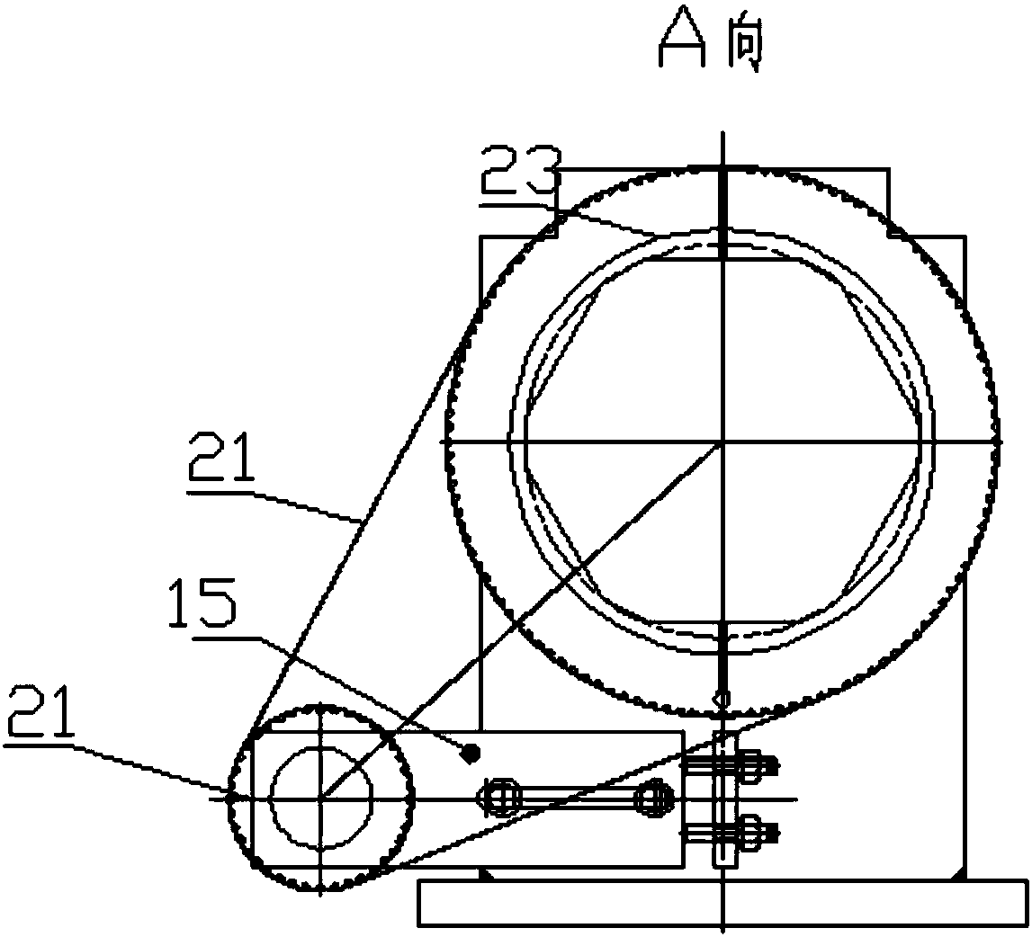
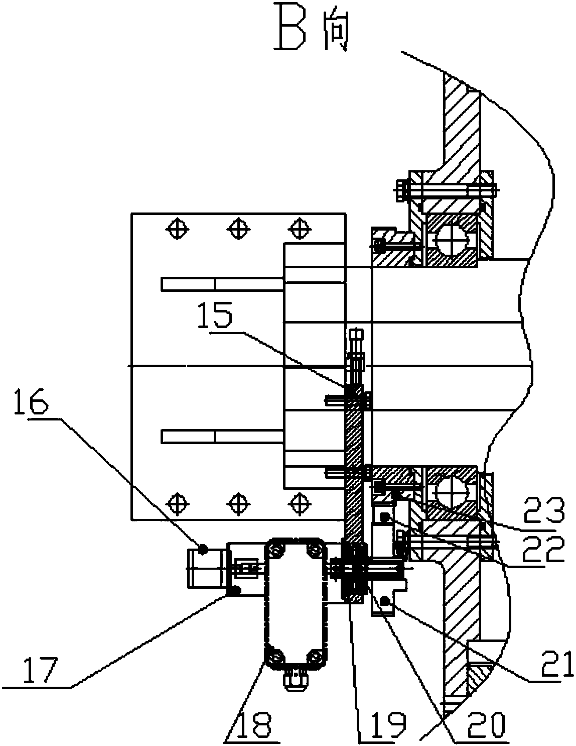
[0028] like figure 1 , figure 2 , image 3 , Figure 4 and Figure 5 As shown, a motor reel integrated lifting device structure, the hollow main shaft 5 passes through the stator core a 3, the stator core b 7 and the end cover 9, the stator core a 3 and the stator core b 7 are respectively arranged on the hollow main shaft 5 Both ends form an independent and unified motor stator. The lifting drum 1 is arranged outside the stator core a 3 and the stator core b 7, and the ends of the stator core a 3 and the stator core b 7 are respectively provided with stator coils a 4 and stator coil b 8, permanent magnet a 2 and permanent magnet b 6 are arranged inside the lifting reel 1; the end cover 9 is fixed on both sides of the lifting reel 1, and a main Bearing 14, the two ends of main bearing 14 are provided with shaft seal 10 and oil seal 11, and oil ...


PUM


Abstract

The invention belongs to the technical field of motor and crane manufacturing, and provides a motor and winding drum integrated lifting device structure. A hollow main shaft penetrates through a stator iron core a, a stator iron core b and end covers. A lifting winding drum is arranged outside the stator iron core a and the stator iron core b. A stator coil a and stator coil b are separately arranged at the ends of the stator iron core a and the stator iron core b. A permanent magnet a and a permanent magnet b are arranged inside the lifting winding drum. The end covers are fixed on both sidesof the lifting winding drum. Rigid supporting seats are further fixedly connected with two ends of the hollow main shaft. Large synchronous wheels are fixed on an oil seal. Synchronous wheel mountingseats are fixed on the rigid supporting seats. Small synchronous wheels are fixed on the synchronous wheel mounting seats. The small synchronous wheels are connected with the large synchronous wheelsthrough synchronous belts. Height limiting stoppers are connected with the small synchronous wheels through auxiliary shafts. Encoders are connected with the height limiting stoppers through elasticcouplings. According to the motor and winding drum integrated lifting device structure, the production and assembly process of the permanent magnets is simplified, the deformation of the main shaft isreduced, and it is guaranteed that the motor can operate reliably.

Description

technical field [0001] The invention belongs to the technical field of motor and crane manufacturing, and mainly relates to motors and cranes, in particular to a motor reel integrated lifting device structure. Background technique [0002] The motor reel integrated lifting device has the advantages of small size, light weight, simple structure, high efficiency, and direct drive control. It is suitable for applications with low speed and high torque. be widely used. [0003] In some special lifting occasions, if the lifting height is relatively high, that is, high head, for the motor-drum integrated lifting device, there must be a drum long enough to accommodate the wire rope due to the height, that is, the length of the drum. rope capacity. But for the motor, the stator core does not need to be so long, but the rotating shaft of the motor needs to match the reel. If the stator of the motor is installed in the middle of the rotating shaft, the process of assembling the per...

Claims


Application Information

Patent Timeline
Patent Type & Authority Applications(China)
IPC IPC(8): B66D1/12B66D1/28H02K7/14
CPCB66D1/12B66D1/28H02K7/14
Inventor 马鑫韩雪岩贾建国宁杰张超
Owner SHENYANG POLYTECHNIC UNIV
Learn More