Novel camshaft position sensor

A camshaft and sensor technology, applied in the field of sensors, can solve the problems of low measurement reliability and precision, low sensor output precision, etc., and achieve the effects of strong anti-interference ability, reliable output signal and good stability

Pending Publication Date: 2018-08-24
LAIWU HUANQIU AUTOMOTIVE PARTS
View PDF0 Cites 0 Cited by
  • Summary
  • Abstract
  • Description
  • Claims
  • Application Information

AI Technical Summary

Problems solved by technology

However, the output accuracy of the existing conventionally designed camshaft position sensor is not high. It is often necessary for the engine camshaft to rotate 3 to 10 times in advance before the sensor can output a stable signal. It can be seen that the measurement reliability and accuracy are not high.

Method used


Image

  • Novel camshaft position sensor

Examples


Embodiment Construction

[0016] The specific implementation manner of the present invention will be further described below in conjunction with the accompanying drawings. Wherein the same components are denoted by the same reference numerals. It should be noted that the words "front", "rear", "left", "right", "upper" and "lower" used in the following description refer to the directions in the drawings, and the words "inner" and "outer ” refer to directions towards or away from the geometric center of a particular part, respectively.

[0017] In order to make the content of the present invention more clearly understood, the technical solutions in the embodiments of the present invention will be clearly and completely described below in conjunction with the drawings in the embodiments of the present invention.

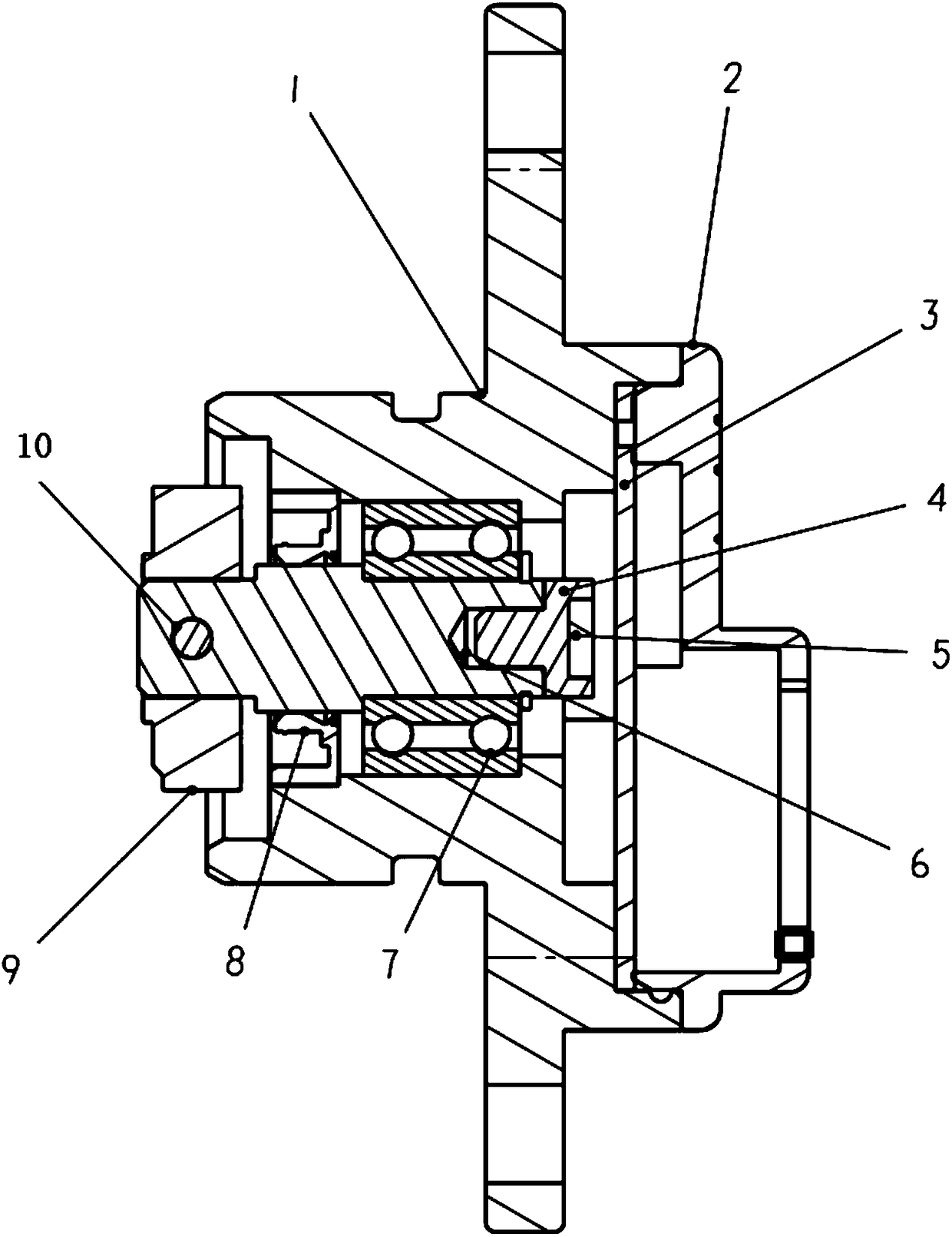
[0018] like figure 1 As shown, a new type of camshaft position sensor includes: a housing 1 and a back cover 2 cooperating with the housing 1, an integrated circuit board 3 is arranged between...


PUM


Abstract

The invention provides a novel camshaft position sensor which comprises a shell and a rear cover, wherein the rear cover is matched and connected with the shell. An integrated circuit plate is arranged between the rear cover and the shell, and a magnet base is arranged in the inner part of the shell. A magnet is arranged at one end, near the rear cover, of the magnet base, and a shaft is inlaid inone end, far away from the rear cover, of the magnet base. The shaft is sleeved with a rolling bearing, and one end, far away from the rear cover, of the shaft is sleeved with a coupler. The novel camshaft position sensor has the advantages of simple structure, good stability and strong anti-interference capability.

Description

technical field [0001] The invention relates to a sensor, in particular to a novel camshaft position sensor. Background technique [0002] The camshaft position sensor is also called the cylinder identification sensor. The function of the camshaft position sensor is to collect the position signal of the valve camshaft and input it to the ECU, so that the ECU can identify the compression top dead center of cylinder 1, so as to perform sequential fuel injection control and ignition timing. control and deflagration control. In addition, the camshaft position signal is also used to identify the first ignition moment when the engine is started. Because the camshaft position sensor can identify which cylinder piston is about to reach the top dead center, it is called a cylinder identification sensor. [0003] At present, the Hall sensor technology is the most mature. Through the Hall effect, the sensor chip collects and outputs signals to the ECU, so as to realize the smooth ign...

Claims


Application Information

Patent Timeline
IPC IPC(8): F02B77/08G01B7/00
CPCF02B77/08G01B7/00
Inventor 马奇张建路新学刘红旭王玉焕
Owner LAIWU HUANQIU AUTOMOTIVE PARTS
Why Eureka
Try Eureka