Seesaw type iron cylinder high-lift air compression water conveying device

A high-lift, see-saw technology, which is applied to the components of the pumping device for elastic fluids, the variable-capacity pump components, the machine/engine, etc. To achieve the effect of high lift

Inactive Publication Date: 2018-08-24
贵池区止十工艺品厂
View PDF0 Cites 0 Cited by
  • Summary
  • Abstract
  • Description
  • Claims
  • Application Information

AI Technical Summary

Problems solved by technology

[0002] Existing water pumps cannot change their position with the rise and fall of the water surface, and can only be placed in deep water. If you want to pump water from shallow water, you need to adjust the position of the pump frequently, which is troublesome; and the existing water pump has a limited lift. When sending water at high places, multi-stage pumps may be required to achieve

Method used


Image

  • Seesaw type iron cylinder high-lift air compression water conveying device
  • Seesaw type iron cylinder high-lift air compression water conveying device
  • Seesaw type iron cylinder high-lift air compression water conveying device

Examples


Embodiment 1

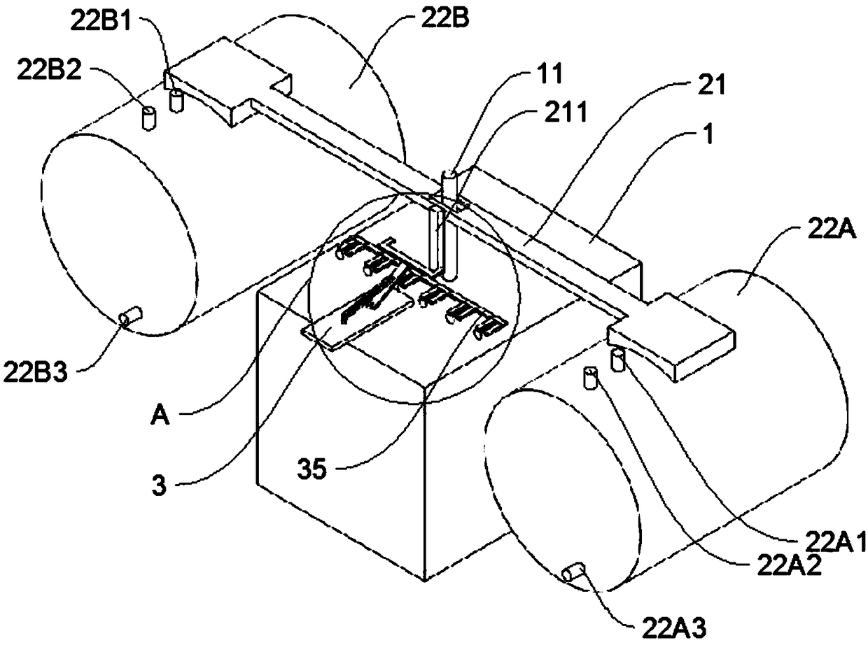
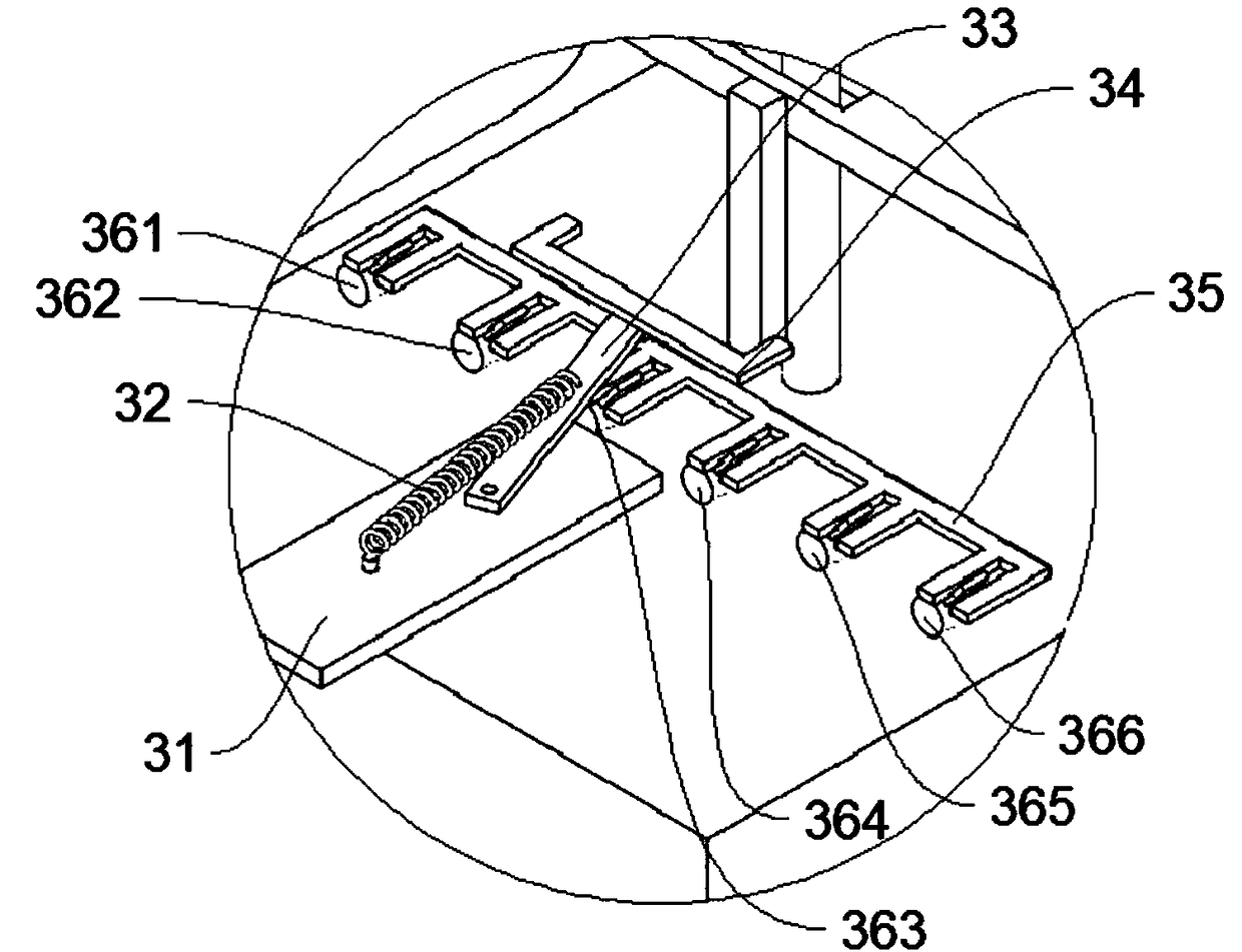
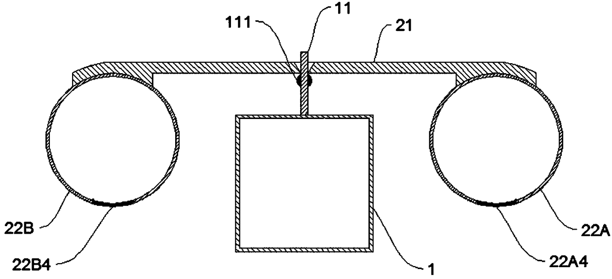
[0017] A seesaw type iron cylinder high-lift air pressure water supply device, comprising a buoyancy tank 1, a support rod 11 is arranged in the middle of the top surface of the buoyancy tank 1, and the middle part of the seesaw rod 21 passes through the support rod 11 through a through hole and can be connected with the support rod 11 The two ends of the seesaw rod 21 respectively fix the first iron cylinder 22A and the second iron cylinder 22B, and the bottoms of the first iron cylinder 22A and the second iron cylinder 22B are respectively provided with a first water inlet 22A4 and a second water inlet 22B4, the middle part of the seesaw bar 21 is provided with a vertically downwardly arranged driving lever 211, and the top surface of the buoyancy tank 1 is also provided with a spring machine 3 and a valve. 33. The middle part of the swing rod 33 is connected to the bottom plate 31 through the spring 32, the lower part of the swing rod 33 is pivotally connected with the long ...

Embodiment 2

[0026] Such as Figure 4 As shown, the difference between this embodiment and Embodiment 1 is that the structure of the driving rod 211 is different from that of the long connecting rod 35; The lower part is provided with a shift fork structure, and the long connecting rod 35 is provided with two fork blocks 351 to replace the second shift fork in embodiment 1, the space between the two fork blocks 351, when the fork 35 is When the driving lever 211 slowly rotates towards the 12 o'clock direction, the pendulum 35 moves in the space between the bar stoppers 351, which does not make the long connecting rod 35 move, only the pendulum 35 rotates rapidly immediately after passing the 12 o'clock direction , the swing rod 35 will be in contact with the swing rod stopper 351 to drive the long connecting rod 35 to move, and the long connecting rod 35 will be connected with the handle of the valve to control the valve. The rotation angle of fork 33 is then controlled by the blocking bl...


PUM


Abstract

The invention belongs to the technical field of water conveying equipment, and particularly relates to a seesaw type iron cylinder high-lift air compression water conveying device. The water conveyingdevice comprises a floating box, a supporting rod and a seesaw rod, a first iron cylinder and a second iron cylinder are fixed to the two ends of the seesaw rod, a first water inlet and a second water inlet are formed in the bottoms of the first iron cylinder and the second iron cylinder correspondingly, a poking rod which is arranged vertically downwards is arranged in the middle of the seesaw rod, a spring machine and a valve are further arranged on the top surface of the floating box, the swing of the seesaw rod controls the rotation of the shifting rod, the rotation of the poking rod pokes the swing of the spring machine, the swing of the spring machine controls the switch state of the valve, and the switch state of the valve controls air inflation and deflation and water inlet and drainage of the iron cylinders. The water conveying device has the advantages that the structure is simple, high-lift water conveying is realized, and in addition, the device can be automatically adjusted along with rise and fall of the water level.

Description

technical field [0001] The invention belongs to the technical field of water delivery equipment, and in particular relates to a seesaw type iron cylinder high-lift air pressure water delivery device. Background technique [0002] Existing water pumps cannot change their position with the rise and fall of the water surface, and can only be placed in deep water. If you want to pump water from shallow water, you need to adjust the position of the pump frequently, which is troublesome; and the existing water pump has a limited lift. When sending water to high places, multi-stage water pumps may be required to achieve it. Contents of the invention [0003] The technical problem to be solved by the present invention is to provide a water delivery device with high lift and floating on the water surface. [0004] The technical solution adopted by the present invention is: a seesaw type iron cylinder high-lift air pressure water supply device, including a buoyancy tank, a support ...

Claims


Application Information

Patent Timeline
Patent Type & Authority Applications(China)
IPC IPC(8): F04B53/10F04B53/16F04B53/00
CPCF04B53/10F04B53/00F04B53/16
Inventor 何正华
Owner 贵池区止十工艺品厂
Why Eureka
Try Eureka