Double layer ring microphone array voice enhancement method

A microphone array and voice enhancement technology, applied in the field of signal processing, to achieve high directivity factor and improve robustness

Active Publication Date: 2018-08-24
FOSHAN SHUNDE SUN YAT SEN UNIV RES INST +2
View PDF5 Cites 9 Cited by
  • Summary
  • Abstract
  • Description
  • Claims
  • Application Information

AI Technical Summary

Problems solved by technology

[0005] In order to solve the above problems, the object of the present invention is to provide a double-layer ring microphone array speech enhancement method, which adopts different beamforming me

Method used


Image

  • Double layer ring microphone array voice enhancement method
  • Double layer ring microphone array voice enhancement method
  • Double layer ring microphone array voice enhancement method

Examples


Embodiment Construction

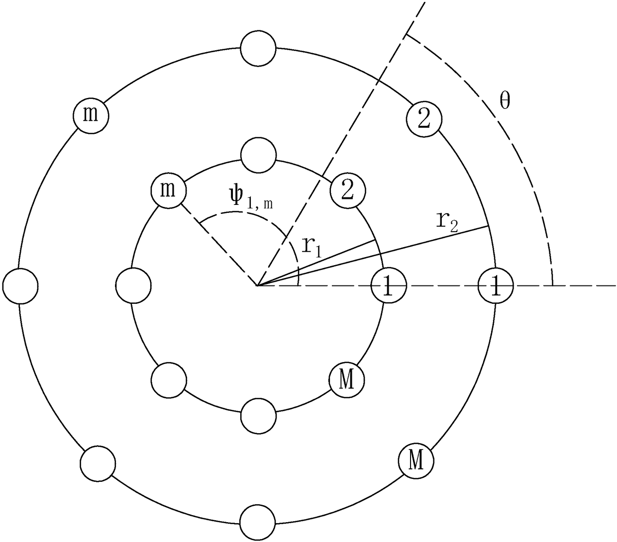
[0042] The microphone array selected by the present invention is a double-layer ring microphone array, and the traditional microphone array is generally a linear structure or a single ring structure. Compared with a linear microphone array, the beam of the ring microphone array can be deflected to multiple directions, and at the same time It has very good frequency consistency, and the single-ring microphone array will have serious spatial aliasing when the number of microphones increases, and this problem can be avoided by using a double-ring structure.

[0043] Due to the presence of two inner and outer circles in the present invention, in order to facilitate the distinction, in the formulas involved below, underlined letters represent double-ring microphones, and letters without underlines represent single-ring microphones, for example d (ω,θ) represents the steering vector of the double-loop microphone, and d p (ω,θ) denotes the steering vector of the single loop microphon...


PUM


Abstract

The invention discloses a double layer ring microphone array voice enhancement method. Different beam forming methods are used according different sound field environments so that the noise robustnessof the microphone array can be enhanced. When the sound field environment is the scattering noise field, the method of combination of first-order and second-order differential beam former items is used at different bands to perform voice enhancement and the high directivity factor can be acquired without sacrificing the white noise gain.

Description

technical field [0001] The invention relates to the technical field of signal processing, in particular to a double-layer circular microphone array speech enhancement method. Background technique [0002] A microphone array is a sound processing system with a specific topology composed of multiple microphones. The information related to the signal and noise collected by it is much larger than that of a single microphone, so it can solve a variety of practical acoustic problems that cannot be handled by a single microphone. [0003] There are many types of noise in the environment, and different speech enhancement algorithms are suitable for different noise fields. Therefore, whether they can adapt to different types of noise fields is an important indicator for evaluating the performance of microphone arrays. For the convenience of research, three abstractions are abstracted. Types of noise fields: coherent noise field, incoherent noise field, and scattered noise field; in a...

Claims


Application Information

Patent Timeline
IPC IPC(8): G10L21/0216G10L21/0232G10L21/0264
CPCG10L21/0216G10L21/0232G10L21/0264G10L2021/02166
Inventor 梅晗张东
Owner FOSHAN SHUNDE SUN YAT SEN UNIV RES INST
Why Eureka
Try Eureka