C-band electrically controlled cavity filter

A cavity filter and C-band technology, which is applied in the field of electronically tuned cavity filters, can solve the problems of Q value deterioration, mechanical frequency hopping filter frequency hopping accuracy error, poor filtering effect, etc., and achieve low Q value. Effects of deterioration, good VSWR, and small in-band insertion loss fluctuations

Inactive Publication Date: 2018-08-24
GUANGDONG SHENGDA ELECTRONICS
View PDF5 Cites 6 Cited by
  • Summary
  • Abstract
  • Description
  • Claims
  • Application Information

AI Technical Summary

Problems solved by technology

Ferrite ESC filter has limited power capacity and large insertion loss, so it is not suitable for high-power RF power front-end and low-noise receiving front-end applications; switched capacitor matrix ESC filter has large power capacity and High tuning speed and other advantages, but its filter order is low, limited out-of-band rejection and poor square coefficient, this type of frequency hopping filter is generally suitable for low frequency band (VHF-S band), and realizes electric tuning filtering in higher frequency band The device requires low capacitance (fF order) high-performance capacitors and high-Q capacitors, so it is difficult to realize
The cavity filter has high power capacity and high Q value. The waveguide cavity mechanically tunable filter is widely used in the RF front-end due to its high quality factor and small insertion loss. However, in the high frequency band, mechanical frequency adjustment will cause In-band matching and deterioration of the Q value in the cavity, when severe, the filter frequency response curve is severely deformed, resulting in poor filtering effect
Due to the thermal expansion and contraction effect of the metal in the cavity filter, the filter frequency band will have temperature drift, which will bring errors to the frequency hopping accuracy of the mechanical frequency hopping filter

Method used


Image

  • C-band electrically controlled cavity filter
  • C-band electrically controlled cavity filter
  • C-band electrically controlled cavity filter

Examples


Embodiment 1

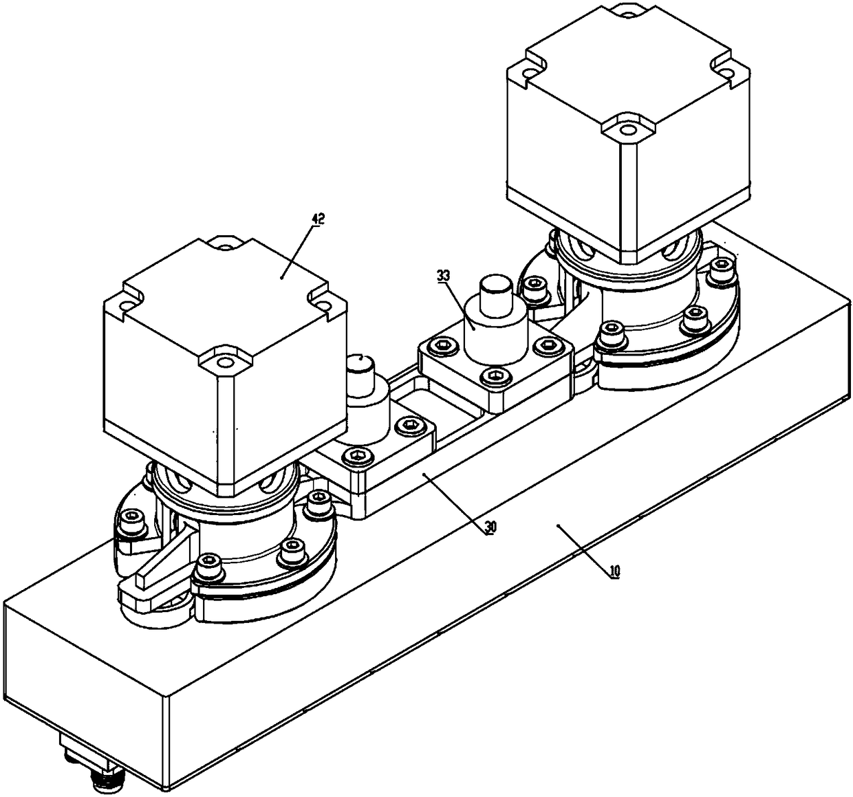
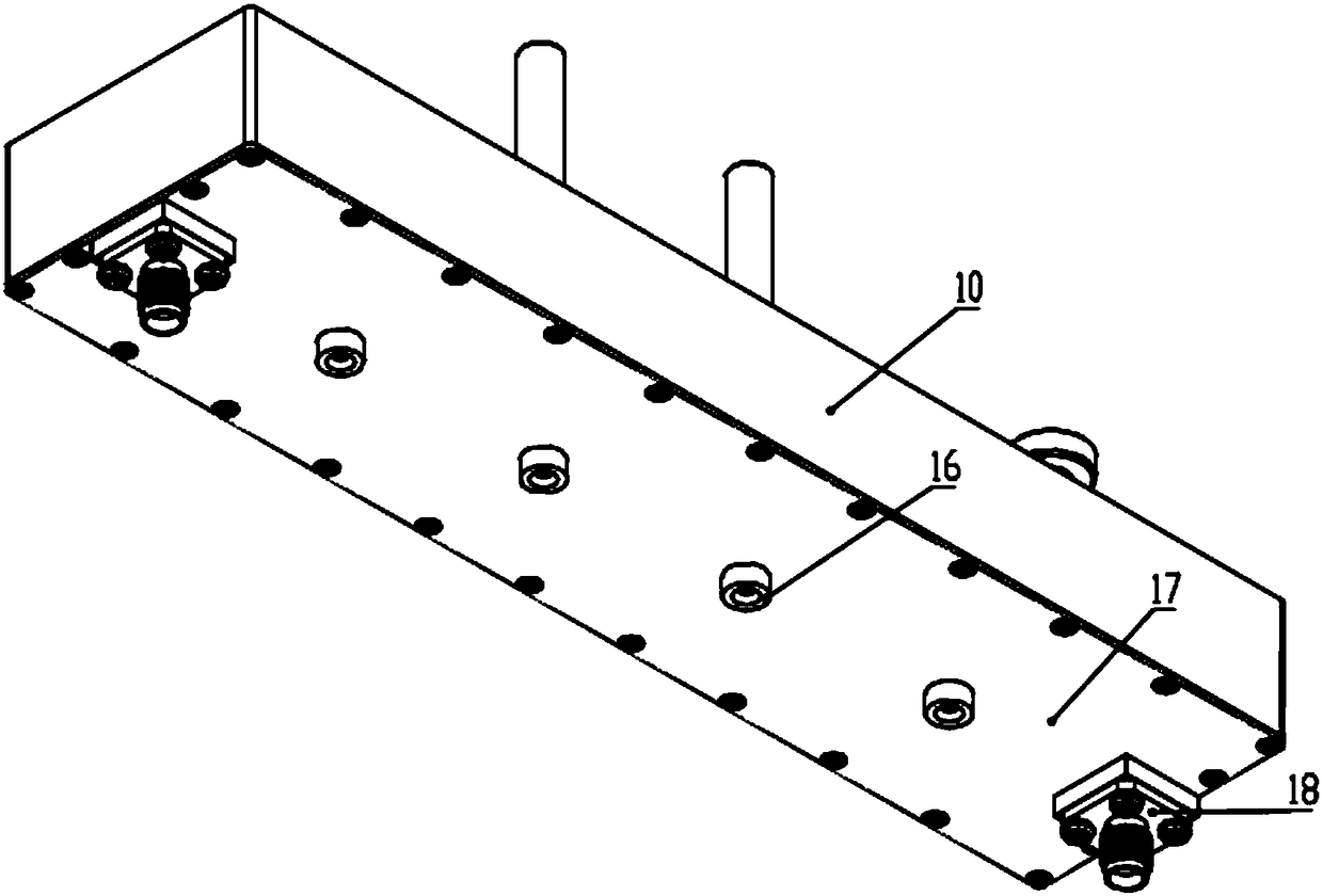
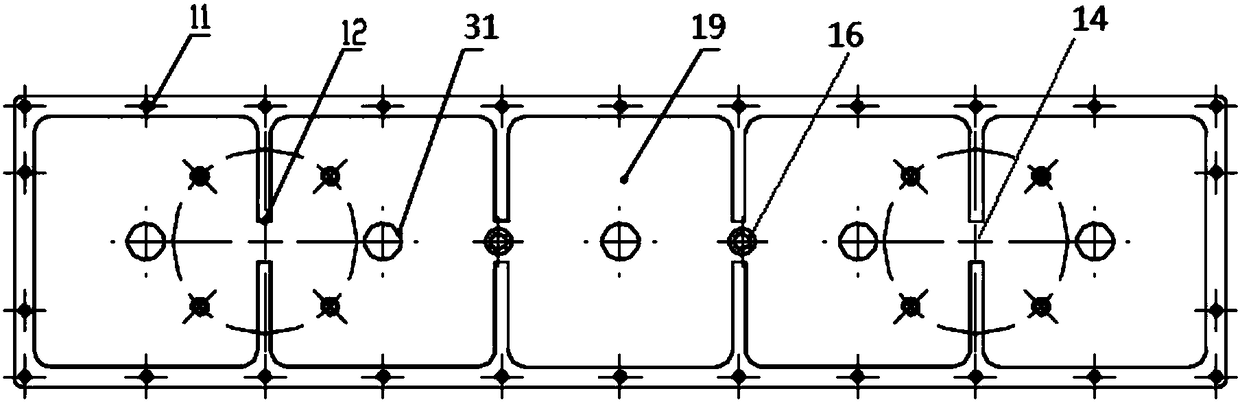
[0031] Embodiment 1, this embodiment is a C-band electronically adjustable cavity filter such as figure 1 As shown, it is mainly divided into three parts: 1) cavity filter; 2) frequency tuning structure 30; 3) motor 42 driving part. The cavity filter is a fifth-order structure in which five resonant cavities 19 resonate with each other. Five frequency tuning columns 31 are located at the center of each resonant cavity 19, and the operating frequency of the filter is adjusted by inserting depth. The tuning columns 31 are all fixed on the tuning bracket 35, and the up and down movement of the tuning bracket 35 is realized by the screw 50 of the stepping motor 42 and the transmission structure of the encrypted high-precision screw thread 304 on the tuning bracket 35, in order to ensure the horizontal position of the tuning bracket 35 Stable and motionless, two linear bearings 33 are set in the middle of the tuning bracket 35, so that the tuning bracket 35 can only move up and dow...


PUM

PropertyMeasurementUnit
Depthaaaaaaaaaa

Abstract

The invention provides a C-band electrically controlled cavity filter, including a cavity filter and a tuning mechanism driven by a motor. The cavity filter comprises a rectangular cavity having a cover plate. Two ends of the cover plate are respectively provided with input and output joints of the filter. In the rectangular cavity, separating plates extend inward from the side walls of the rectangular cavity. The separating plates divide the rectangular cavity into a group of rectangular resonant cavities. The gap between the separating plates on two sides forms a coupling window between adjacent resonant cavities. The cover plate is provided with a coupling strength fine adjustment screw toward the coupling window. A tuning hole communicated with each resonant cavity is arranged on a cavity surface on the opposite side of the cover plate. The tuning mechanism is arranged on the cavity surface. Under control of the tuning mechanism, a tuning column extends into the resonant cavities from the tuning hole, to realize tuning. Design of the C-band electrically controlled cavity filter is based on a coupling bandwidth method, and through rationally selecting a coupling structure between filter cavities, in-band matching is maintained in frequency modulation of the filter, and a Q value in the cavity is deteriorated.

Description

technical field [0001] The present invention relates to the field of electronically tuned cavity filters, in particular to a C-band electrically tuned cavity filter, which has the advantages of low insertion loss, good rectangular coefficient in the whole frequency band, high frequency tuning accuracy and high power capacity. C-band electronically tuned cavity filter. Background technique [0002] The most commonly used filter in a general communication system is a band-pass filter, which only allows useful signals to pass through, while other useless signals, whether they are self-interfering signals or intentional interfering signals of the communication system, are effectively filtered out. This plays a very important role in the good reception of communication equipment and is the most effective means to deal with electromagnetic interference. For tunable filters, not only has the above characteristics, but also can flexibly change the passband frequency according to th...

Claims


Application Information

Patent Timeline
IPC IPC(8): H01P1/207
Inventor 马向华卜景鹏裴旭潮蔡壮华
Owner GUANGDONG SHENGDA ELECTRONICS
Why Eureka
Try Eureka