Quickly cooled long-life conical rotor motor

A conical rotor, rapid cooling technology, used in cooling/ventilation devices, electrical components, electromechanical devices, etc., can solve the problem of heat difficulty, prolong the service life, enhance the heat dissipation effect, and ensure the effect of heat dissipation

Pending Publication Date: 2018-08-24
河南泓之泰实业有限公司
View PDF5 Cites 4 Cited by
  • Summary
  • Abstract
  • Description
  • Claims
  • Application Information

AI Technical Summary

Problems solved by technology

[0006] In order to solve the problem that the conical rotor motor in the prior art tends to generate a large amount of heat and is difficult to cool quickly, the present invention provides a fast cooling long-life conical rotor motor

Method used


Image

  • Quickly cooled long-life conical rotor motor
  • Quickly cooled long-life conical rotor motor
  • Quickly cooled long-life conical rotor motor

Examples


Embodiment 1

[0039] As a basic example:

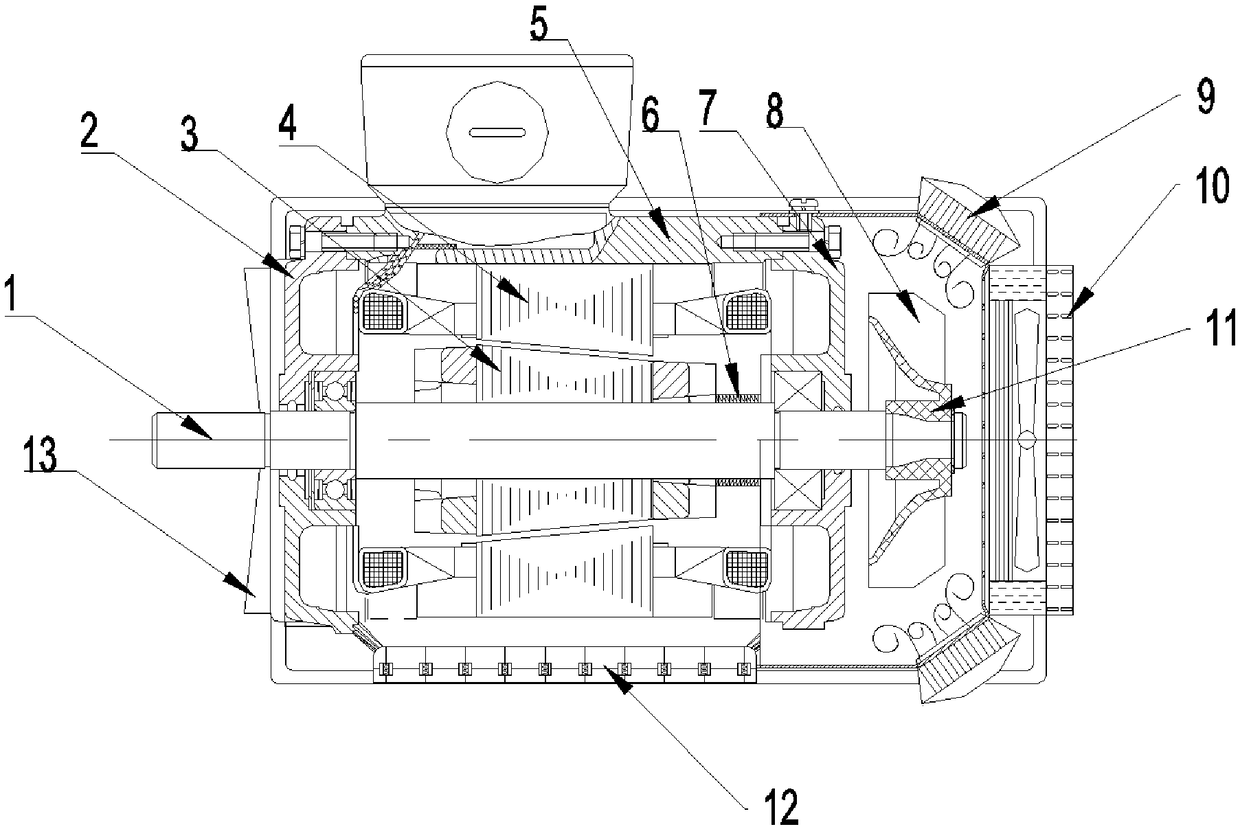
[0040] A fast-cooling long-life conical rotor motor includes a housing 5 and a rotating shaft 1, the rotating shaft 1 is arranged inside the housing 5, the inner wall of the housing 5 is connected with a stator 4, and the inner cavity of the stator 4 is Conical, the rotor 3 is installed on the rotating shaft 1, the shape of the rotor 3 is conical, the front end of the rotating shaft 1 is equipped with a front end cover 2, it is characterized in that the rear end of the rotating shaft 1 is connected with a fan brake wheel 11, so The housing 5 around the fan brake wheel 11 is connected with a corner-end heat transfer head 9, and the rear end of the housing 5 is connected with a brake cooling device 10, and an exhaust blade 17 is installed in the braking cooling device 10. The brake cooling device 10 is also connected with a liquid cooling tube.

[0041] The outer wall of the housing 5 covered by the brake cooling device 10 is provided with a plurali...

Embodiment 2

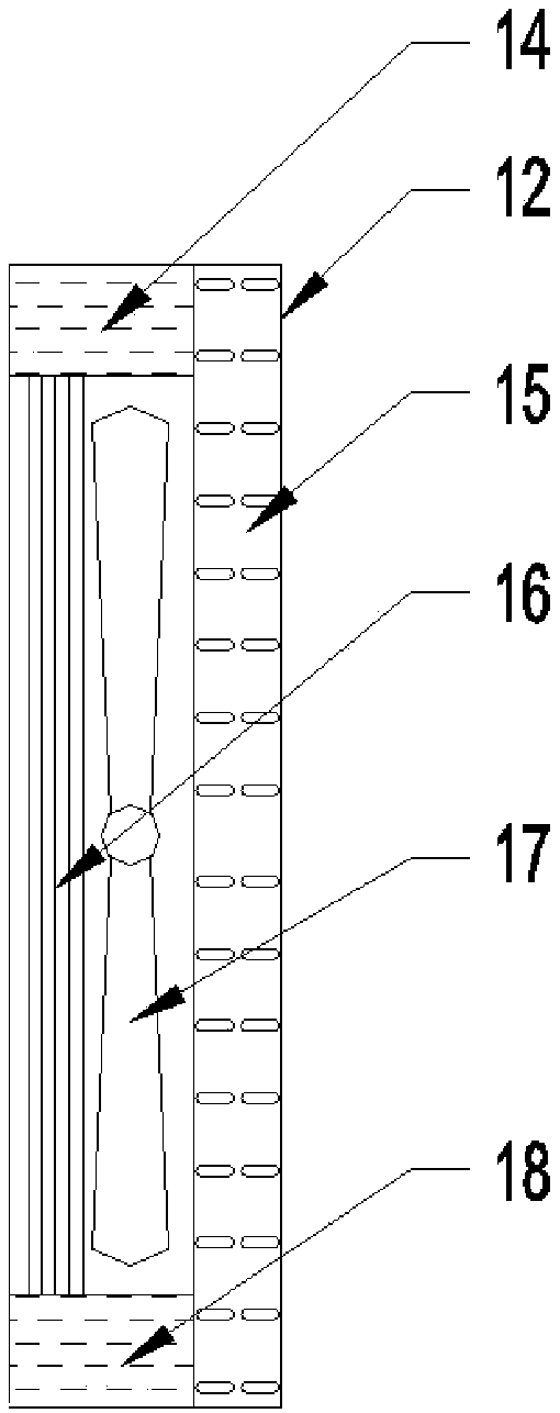
[0043]This embodiment focuses on the improvements compared with the above-mentioned embodiments, and the similarities will not be repeated. In this embodiment, the interior of the brake cooling device 10 includes an upper liquid chamber 14 above and a lower liquid chamber below. chamber 18, and a fan blade 17 is installed between the upper liquid chamber 14 and the lower liquid chamber 18, and both the upper liquid chamber 14 and the lower liquid chamber 18 are connected with the liquid cooling pipe.

[0044] Further, a heat dissipation pipe 16 is connected between the upper liquid chamber 14 and the lower liquid chamber 18, and the heat dissipation pipe 16 is vertically arranged and attached to the housing 5, and the brake cooling device 10 is on the side away from the housing 5. A heat dissipation cover 15 is installed, and the exhaust blade 17 is installed between the heat dissipation pipe 16 and the heat dissipation cover 15, and the heat dissipation cover 15 is provided wi...

Embodiment 3

[0047] This embodiment focuses on the improvements compared with the above-mentioned embodiments, and the similarities will not be repeated. In this embodiment, the corner-end heat-conducting head 9 includes an arc-shaped heat-absorbing sheet 24 at the bottom, and the arc-shaped The heat absorbing sheet 24 is arranged around the fan brake wheel 11 in the housing 5, and the arc-shaped heat absorbing sheet 24 is connected with a thermal transition layer 22 on the inner wall of the housing 5, and a heat conducting sheet is connected above the thermal transition layer 22 23 , the heat conduction sheet 23 divides the inside of the corner-end heat conduction head 9 into a plurality of cavities, and the heat conduction cavity 21 is formed above the heat conduction sheet 23 .

[0048] The separated cavity can make the heat evenly distributed in it, so as to ensure that the heat conducting sheet 23 can quickly conduct heat with the largest effective area, and the arc-shaped heat absorbi...


PUM


Abstract

The invention discloses a quickly cooled long-life conical rotor motor, belongs to the technical field of motors, and solves the problem that in the prior art, a conical rotor motor is prone to generating a large amount of heat, so that the conical rotor motor is difficultly quickly cooled. The quickly cooled long-life conical rotor motor comprises a shell and a rotating shaft. The rotating shaftis arranged inside the shell. A stator is connected onto the inner wall of the shell. The inner cavity of the stator is conical. A rotor is mounted on the rotating shaft, and is conical. A front end cover is mounted at the front end of the rotating shaft. The quickly cooled long-life conical rotor motor is characterized in that a fan brake wheel is connected with the rear end part of the rotatingshaft; an angle end heat conduction head is connected to the shell around the fan brake wheel; a brake cooling device is connected with the rear end of the shell; ventilation blades are mounted in thebrake cooling device; and a liquid cooling pipe is connected with the brake cooling device. The quickly cooled long-life conical rotor motor is good in cooling effect, fast to cool, stable and reliable in operation, and long in service life.

Description

technical field [0001] The invention belongs to the technical field of motors, and in particular relates to a fast-cooling long-life conical rotor motor. Background technique [0002] Conical rotor brake motor is a three-phase asynchronous motor with a tapered stator and rotor with its own brake. The inner cavity of the stator and the outer shape of the rotor are conical motors, which have the ability of self-braking when power is off, and are widely used in lifting equipment such as electric hoists and hoists. Its working principle is: after the stator is energized, a rotating magnetic field is generated, and at the same time, an axial magnetic pull is generated to move the rotor axially and compress the spring, so that the conical ring on the fan brake wheel is separated from the static brake ring, and the rotor starts to rotate. After the stator is de-energized, the axial magnetic pulling force disappears. Under the action of the spring, the rotor resets together with t...

Claims


Application Information

Patent Timeline
Patent Type & Authority Applications(China)
IPC IPC(8): H02K9/06H02K9/22H02K9/19H02K5/24H02K5/20H02K5/18
CPCH02K5/18H02K5/20H02K5/24H02K9/06H02K9/19H02K9/22H02K2213/03
Inventor 杨志伟
Owner 河南泓之泰实业有限公司
Why Eureka
Try Eureka