
Control device for electronic product
A technology for control devices and electronic products, which is applied in the directions of amplified control, electrical components, limiting amplitude, etc., and can solve problems such as affecting the service life of low-voltage electronic products, signal disturbance, and electronic product error messages.
- Summary
- Abstract
- Description
- Claims
- Application Information
AI Technical Summary
Problems solved by technology
Method used
Image


Examples
Embodiment 1
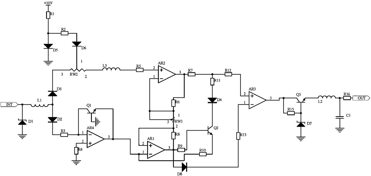
[0013] Embodiment 1, the control device of the electronic product includes a signal receiving circuit, a logarithmic differential feedback circuit and a comparative voltage stabilization output circuit, the signal receiving circuit receives the signal at the input end of the signal transmission channel in the control device of the electronic product, and the logarithmic The differential feedback circuit is divided into two ways to receive the signal output from the receiving circuit, one way is limited by the sliding rheostat RW2 and then input to the non-inverting input terminal of the operational amplifier AR2, and at the same time, the power supply +10V provides the base potential for the non-inverting input terminal of the operational amplifier AR2. The other path is processed by the logarithmic circuit composed of the operational amplifier AR4 and the transistor Q1. The signals output by the logarithmic circuit are respectively the base potential of the inverting input term...
Embodiment 2
[0015] Embodiment 2, on the basis of Embodiment 1, the signal receiving circuit receives the signal at the input end of the signal transmission channel in the control device of the electronic product, the regulator tube D1 has the effect of stabilizing the voltage, the inductor L1 filters, and one end of the inductor L1 Connect to the anodes of diode D3 and diode D2, the other end of inductor L1 is connected to the signal output port and the negative pole of regulator D1, and the anode of regulator D1 is grounded.
[0016]Implementation 3, on the basis of Embodiment 1, the comparison voltage stabilizing output circuit receives the output signal of the logarithmic differential feedback circuit, and the comparator AR3 compares the signals, and a voltage stabilizing circuit composed of the triode Q3 and the voltage stabilizing tube D7 is designed to stabilize the voltage , to further stabilize the signal, and design an LC circuit composed of inductance L2 and capacitor C1 in paral...
PUM
 Abstract
Description
Claims
Application Information