Sprinkling irrigation robot

A technology for robots and hydro-generators, applied in the directions of machines/engines, mechanical equipment, engine components, etc., can solve the problems of limited use, troublesome electricity consumption, single irrigation mode, etc., and achieve the effect of reducing the output of electricity and improving the range.

Pending Publication Date: 2021-04-30
YUNNAN COLLEGE OF BUSINESS MANAGEMENT
View PDF5 Cites 2 Cited by
  • Summary
  • Abstract
  • Description
  • Claims
  • Application Information

AI Technical Summary

Problems solved by technology

[0004] The purpose of the present invention is to solve the problems of electricity consumption in the prior art, and at the same time, most sprinkler irrigation robots have a single sprinkler irrigation mode, which leads to limited use, and the inability to automatically collect rainwater and the shortcomings of low resource utilization, and proposes a irrigation robot

Method used


Image

  • Sprinkling irrigation robot
  • Sprinkling irrigation robot
  • Sprinkling irrigation robot

Examples


Embodiment 1

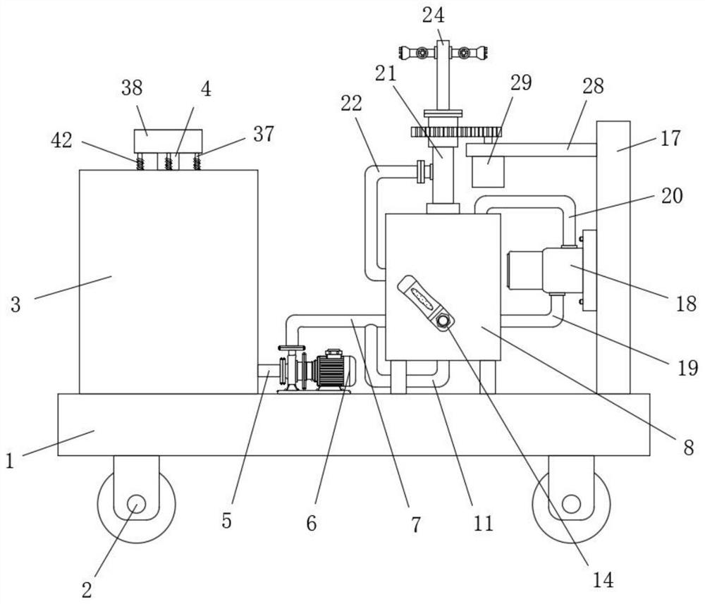
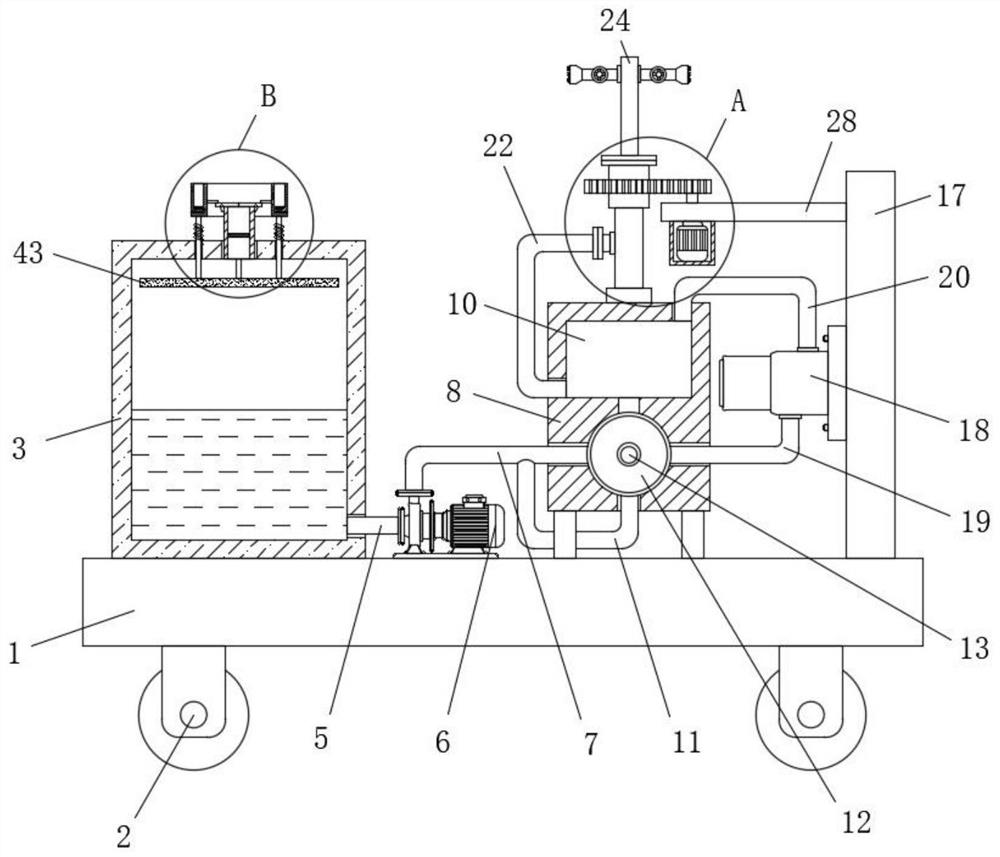
[0037] refer to Figure 1-Figure 8 , a sprinkler robot, comprising a base plate 1, four corners of the bottom of the base plate 1 are provided with walking wheels 2, it is characterized in that the top side of the base plate 1 is fixedly connected with a water storage tank 3, and the top of the water storage tank 3 is provided with a water injection pipe 4. A suction pipe 5 is provided at the bottom of one side of the water storage tank 3, and one end of the suction pipe 5 extends to the outside of the water storage tank 3 and is flange-connected with a water pump 6, and the outlet end of the water pump 6 is connected with a water delivery pipe 7. The other end of 7 communicates with a water tank 8, and the inside of the water tank 8 is respectively provided with a circular chamber 9 and a rectangular chamber 10, and the circular chamber 9 is located below the rectangular chamber 10 and communicates with one end of the water delivery pipe 7, and the water delivery pipe The bot...

Embodiment 2

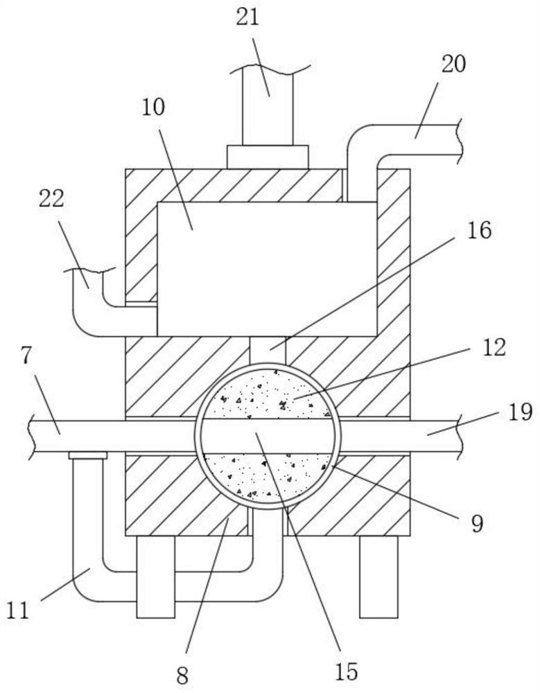
[0039] This embodiment is further improved on the basis of Embodiment 1: one side of the valve ball 12 is fixedly connected with a rotating shaft 13, one side of the rotating shaft 13 runs through one side of the water tank 8 and is fixedly covered with a handle 14, one side of the valve ball 12 A water flow channel 15 is opened on the side, and the two ends of the water flow channel 15 are respectively connected with one end of the water delivery pipe 7 and one end of the water inlet pipe 19, and the top inner wall of the circular cavity 9 and the bottom inner wall of the rectangular cavity 10 are provided with the same flow port. 16, and the flow port 16 and one end of the U-shaped pipe 11 are respectively connected and cooperated with the two ends of the water flow channel 15. By turning the handle 14 to drive the valve ball 12 to rotate, the water flow channel 15 can be driven to change direction, and then the direction of the water flow can be changed.

[0040] The water s...


PUM


Abstract

The invention belongs to the technical field of sprinkling irrigation devices, particularly relates to a sprinkling irrigation robot, and provides the following scheme to solve the problems that in the prior art, electricity utilization is troublesome, and most sprinkling irrigation robots are single in sprinkling irrigation mode, so that use is limited, rainwater cannot be automatically collected, and the resource utilization rate is low, the sprinkling irrigation robot comprises a bottom plate, walking wheels are arranged at four corners at the bottom of the bottom plate, and a water storage tank is fixedly connected to one side of the top of the bottom plate. According to the sprinkling irrigation robot, electric energy can be generated and a motor can be started when water flow flows through a hydroelectric generator, then the effect of rotary sprinkling irrigation of a spray head can be achieved, the direction of the water flow can be changed by rotating a handle, then the motor can stop working, and the effect of directional sprinkling irrigation of the spray head can be realized; and meanwhile, the overall weight is changed through collection and leakage of rainwater by a movable ring, and automatic opening and closing of a water injection pipe can be achieved, so that the automatic rainwater collection effect is achieved, and the practicability and the full resource utilization are improved.

Description

technical field [0001] The invention relates to the technical field of sprinkler irrigation devices, in particular to a sprinkler irrigation robot. Background technique [0002] Sprinkler irrigation is an irrigation method in which water with a certain pressure is sprayed into the air with the help of water pumps and pipeline systems or by using the drop of natural water sources, and then scattered into small droplets or formed into mist to fall on the plants and the ground. It saves water and does not damage the soil. The structure, the adjustment of the ground climate and the advantages of not being restricted by the terrain. As water resources become less and less, sprinkler irrigation becomes more and more important, so there are various sprinkler irrigation robots on the market for sprinkler irrigation work. [0003] Since the sprinkler irrigation work is mostly carried out in the outdoor field, it is troublesome to use electricity for electrical equipment. At the same...

Claims


Application Information

Patent Timeline
Patent Type & Authority Applications(China)
IPC IPC(8): A01G25/09A01G25/16E03B3/02F03B13/00
CPCA01G25/09A01G25/16E03B3/02F03B13/00Y02A20/108Y02A40/22
Inventor 钟赛君
Owner YUNNAN COLLEGE OF BUSINESS MANAGEMENT
Why Eureka
Try Eureka