A valve timing switch using a mechanical transmission structure and a method of using the same

A technology of mechanical transmission and switch, applied in the direction of mechanical equipment, lift valves, valve details, etc., can solve the problems of failure of timing effect, relatively large resistance, and inability to drive gears to rotate, so as to simplify the use steps and reduce resistance Effect

Active Publication Date: 2022-08-09
苏州市东挺河智能科技发展有限公司
View PDF5 Cites 0 Cited by
  • Summary
  • Abstract
  • Description
  • Claims
  • Application Information

AI Technical Summary

Problems solved by technology

[0004] However, in the above scheme, the shifting block is controlled to move between the first position and the second position through the gear and some racks with meshing teeth, that is, the gear rack is driven by the rotation of the gear to move the shifting block, that is, the valve The spool moves, and then if the flow rate of the circulating medium (such as liquid or gas) inside the valve is fast, when the valve is closed, the resistance encountered by the spool is relatively large, so in combination with the above scheme, through the wind-up timer (The clockwork timer is equivalent to a kind of mechanical timer. Its principle is to use the spring as the driving force, use the escapement governor to control the travel time accuracy, and through the gear transmission and the cam, it is operated according to the time period preset by the time control mechanism. For the action of the mechanism, please refer to the output shaft of the document http: / / www.hqps.com / tech / 201408 / 210828.html) to drive the gear to rotate. It can be seen that the principle of the wind-up timer is usually to use the belt spring (spring) to restore the deformation The released energy is used as the energy source, and since the gear rotation in the above scheme needs to directly drive the valve core to move, then the resistance encountered during the rotation of the clockwork timer output shaft is relatively large, so there is a belt spring (spring) The phenomenon that the provided energy cannot drive the gear to rotate, which leads to the failure of the entire timing effect

Method used


Image

  • A valve timing switch using a mechanical transmission structure and a method of using the same
  • A valve timing switch using a mechanical transmission structure and a method of using the same
  • A valve timing switch using a mechanical transmission structure and a method of using the same

Examples


Embodiment Construction

[0024] The technical solutions in the embodiments of the present invention will be clearly and completely described below with reference to the accompanying drawings in the embodiments of the present invention. Obviously, the described embodiments are only a part of the embodiments of the present invention, rather than all the embodiments. Based on the embodiments of the present invention, all other embodiments obtained by those of ordinary skill in the art without creative efforts shall fall within the protection scope of the present invention.

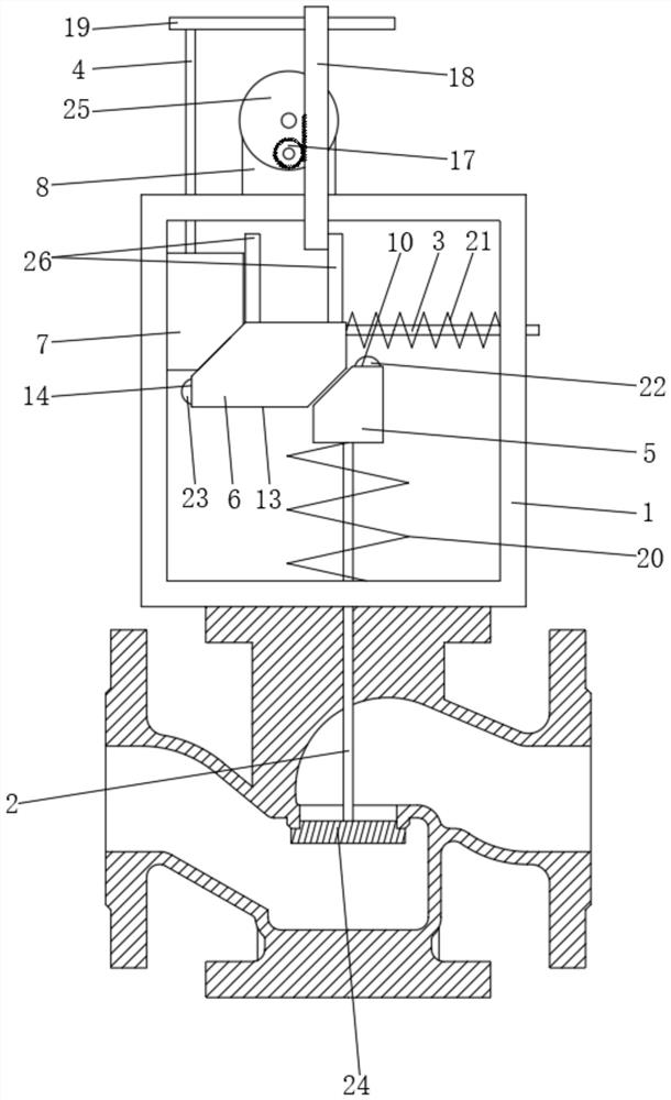
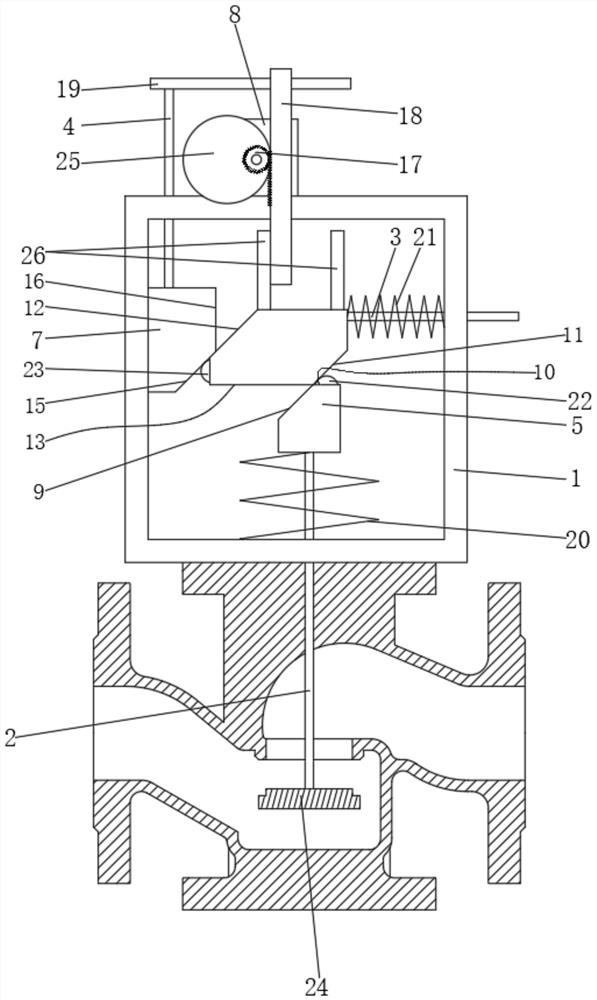
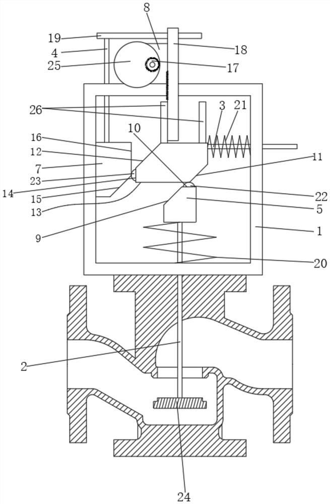
[0025] see Figure 1 to Figure 3 , the present invention provides a kind of technical scheme:

[0026] A valve timing switch with a mechanical transmission structure includes a control mechanism for controlling the up and down movement of the valve core 24, and a timing driver for timing the control mechanism. Limit rod two 3 and limit rod three 4, one end of limit rod one 2 is fixedly connected with valve core 24, the other end of ...


PUM


Abstract

The invention discloses a valve timing switch adopting a mechanical transmission structure and a method for using the same, and relates to the technical field of valve opening and closing. The mechanism includes a limit rod 1, a limit rod 2 and a limit rod 3 that penetrate through the bracket. One end of the limit rod 1 is fixedly connected with the valve core, and the other end of the limit rod 1 is fixedly connected with a pressing block 1. The limit The end of the rod 2 is fixedly connected with a pressing block 2, the end of the limit rod 3 is fixedly connected with a pressing block 3, the bracket is provided with a reset part 1 for resetting the pressing block 1, and the bracket is also provided with a pressing block 1. The reset part 2 of the pressing block 2 resets, and the reset part 1 is used as the driving source when the valve core moves up, and as the driving source when the valve is closed. The present invention solves the technical problems raised in the background art through the cooperation of the above-mentioned structures.

Description

technical field [0001] The invention relates to the technical field of valve opening and closing, in particular to a valve timing switch adopting a mechanical transmission structure and a method of using the same. Background technique [0002] Valves are usually used to open and close pipeline accessories. Most of the common valves on the market need to manually control the on-off of water flow. If the valve is not closed tightly, water resources will be wasted. Due to the high frequency of use, it is easy to cause ineffective induction, thereby causing water leakage. [0003] For example, a transmission mechanism for a mechanical timing valve disclosed in Chinese patent CN201710128344.4, publication date: 20170623, the invention is set between the main shaft of the timer and the valve core for driving the valve, and the mechanism includes a piece of The mounting plate, the gear coaxially and fixedly installed with the main shaft, and the dial fixedly installed with the val...

Claims


Application Information

Patent Timeline
Patent Type & Authority Patents(China)
IPC IPC(8): F16K31/48F16K1/00
CPCF16K31/48F16K1/00
Inventor 林瑞汉
Owner 苏州市东挺河智能科技发展有限公司
Why Eureka
Try Eureka