
Patsnap Eureka
For R&D, Patsnap Eureka makes reading and utilizing patents & technical documents easy.
Patsnap Eureka AIR
Designed for self-driven R&D workflows. Generate viable solutions, solve complex R&D challenges, empower your innovation with AI.

Patsnap Eureka Materials
Designed for material experts only. Revolutionize your material R&D, from search, analyze, to developing new materials.

TechResearch
Generate reliable direction feasibility study reports for your R&D in just a few steps.

TechSeek
Discover and master advanced knowledge NOW. Basics, ideas, possibilities, all at once.

TechMind
As an expert in R&D Theories, TechMind can generates customized viable solutions instantly.

TechRisk
Analyze your overall solution with one click, know your potential R&D risks in advance.

TechMonitor
Get weekly tech updates, stay abreast of the latest tech innovations and key insights.
Camera configuration method and device
A configuration method and camera technology, applied in the field of computer vision, can solve the problem of not considering other factors, and achieve the effect of reasonable configuration method, reasonable configuration cost, and reasonable configuration economy.
- Summary
- Abstract
- Description
- Claims
- Application Information
AI Technical Summary
Problems solved by technology
Method used
Image

Examples
Embodiment 1
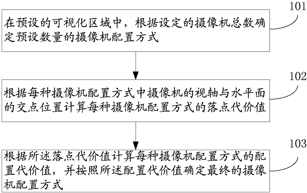
[0036] figure 1 It is a flowchart of a camera configuration method provided in Embodiment 1 of the present invention. The execution subject of this embodiment may be a computer device or a functional unit in the computer device. This embodiment specifically includes steps S101 to S103, which are described in detail as follows:
[0037] S101: In the preset visualization area, determine a preset number of camera configuration methods according to the set total number of cameras.
[0038] The preset visualization area can be any size created by the user in the optical motion capture system, and contains the simulated area of obstacles such as columns and walls. In the preset visualization area, users can further set camera parameters, including setting the total number of cameras, etc. Among them, the total number of cameras set can be actually adjusted.
[0039] The camera configuration mode can be determined according to the camera parameters set by the user. According to ...
Embodiment 2
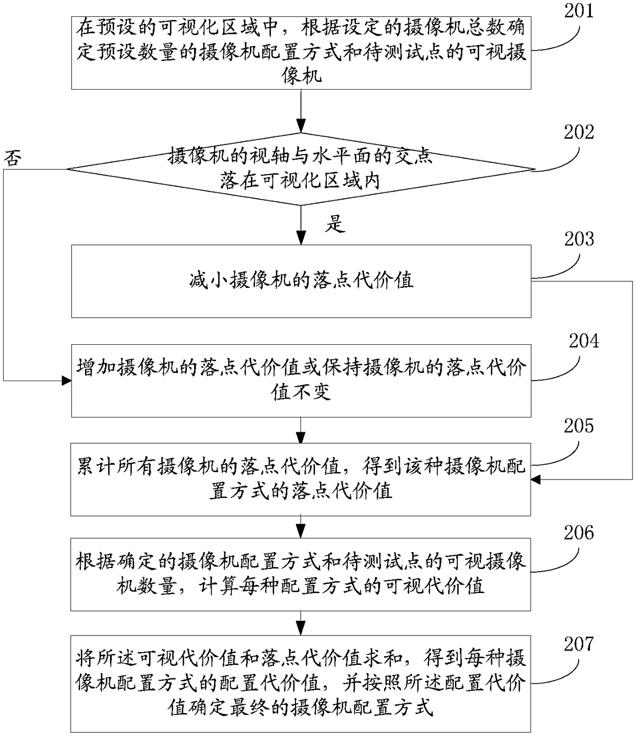
[0050] figure 2 It is a flowchart of a camera configuration method provided in Embodiment 2 of the present invention. The execution subject of this embodiment may be a computer device or a functional unit in the computer device. This embodiment specifically includes steps S201 to S208, which are described in detail as follows:
[0051] S201: In the preset visualization area, determine a preset number of camera configuration modes and visible cameras of the points to be tested according to the set total number of cameras.
[0052] The preset visualization area can be any size created by the user in the optical motion capture system, and contains the simulated area of obstacles such as columns and walls. In the preset visualization area, users can further set camera parameters, including setting the total number of cameras, etc. Among them, the total number of cameras set can be actually adjusted.
[0053] The camera configuration mode can be determined according to the cam...
Embodiment 3
[0069] Figure 4 It is a flow chart of a camera configuration method provided by Embodiment 3 of the present invention. For Embodiment 3, reference may be made to Embodiment 2. For steps S401-S406, reference may be made to Steps S201-S206 in Embodiment 2, which will not be repeated here. The difference between the present embodiment and the second embodiment lies in that the calculation of the configuration cost of each camera configuration mode is different.
[0070] Specifically, in the second embodiment, when calculating the configuration cost value of each camera configuration mode according to the determined camera configuration mode and the drop point cost value, specifically, according to the determined camera configuration mode and the availability of the points to be tested Depending on the number of cameras, calculate the visible cost value of the camera configuration mode, and then superimpose the visible cost value and the calculated drop point cost value to obtain...
PUM
 Abstract
Description
Claims
Application Information
 - R&D Engineer
- R&D Manager
- IP Professional
- Industry Leading Data Capabilities
- Powerful AI technology
- Patent DNA Extraction
Browse by: Latest US Patents, China's latest patents, Technical Efficacy Thesaurus, Application Domain, Technology Topic, Popular Technical Reports.
© 2024 PatSnap. All rights reserved.Legal|Privacy policy|Modern Slavery Act Transparency Statement|Sitemap|About US| Contact US: help@patsnap.com