Ultrasonic electromagnetic cooking tool

A cooking utensil and ultrasonic technology, applied in the field of electromagnetic cooking utensils, can solve the problems that the container cannot be removed from the base, poor assembly firmness, and the cooking utensils fall, etc., so as to improve the taste of food, save electric energy, and reduce losses.

Active Publication Date: 2018-08-24
彭志军
View PDF14 Cites 4 Cited by
  • Summary
  • Abstract
  • Description
  • Claims
  • Application Information

AI Technical Summary

Problems solved by technology

The applicant believes that this technical solution has the following deficiencies in practical application: since the vibrating plate is directly fixed on the inner cover, the vibration of the ultrasonic wave to the food container is a form of vibration in the air, and the vibration of the ultrasonic wave It is transmitted to the inner cover first, and then the inner cover is passed to the food container set in the inner cover, and it is passed between the top edge of the inner cover and the top of the food container, and there is a space between the inner cover and the food container. the space of vibration
The container of this solution must be fixedly assembled with the base. It is a one-piece cooking appliance. The container cannot be removed from the base. People cannot replace the container during use, which has great limitations in daily use.
Secondly, the container and the base are fixed and assembled together. When the container receives the high-frequency oscillation energy of the ultrasonic transducer, it will resonate and resonate to the entire cooking utensil, so that the entire cooking utensil also bears the high-frequency oscillation energy of the ultrasonic transducer. , so that the assembly structure of the entire cooking utensil is very easy to loosen, the assembly firmness is poor, and the service life is short
Moreover, the resonance and resonance generated by the ultrasonic transducer make the entire cooking utensil move on the countertop, which may cause the risk of the cooking utensil falling

Method used


Image

  • Ultrasonic electromagnetic cooking tool
  • Ultrasonic electromagnetic cooking tool
  • Ultrasonic electromagnetic cooking tool

Examples


Embodiment Construction

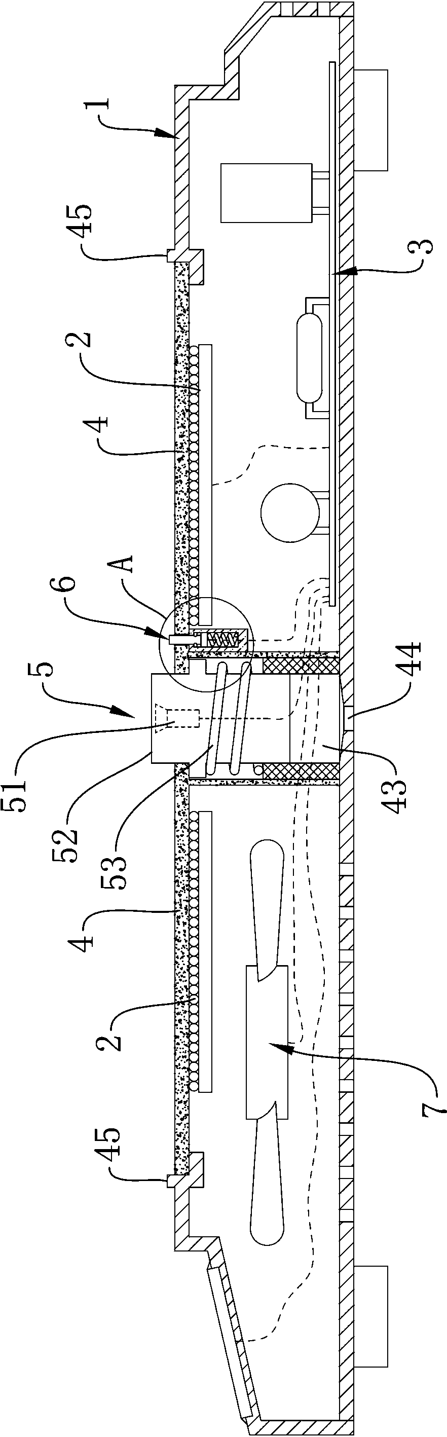
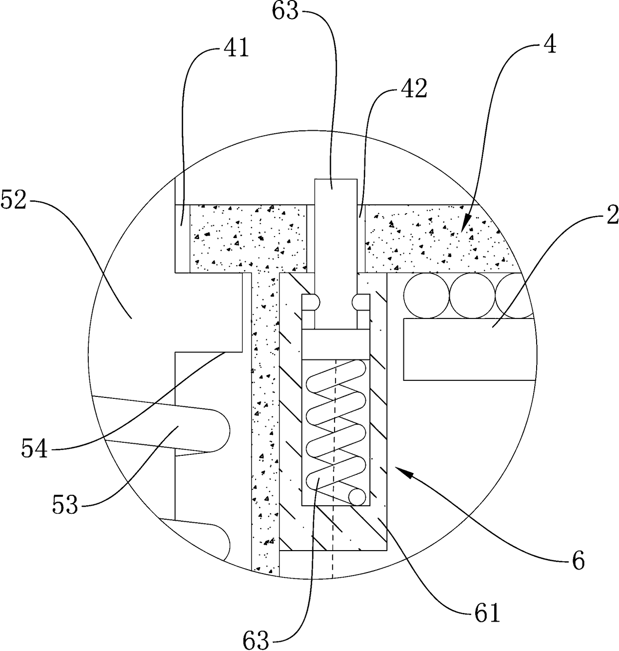
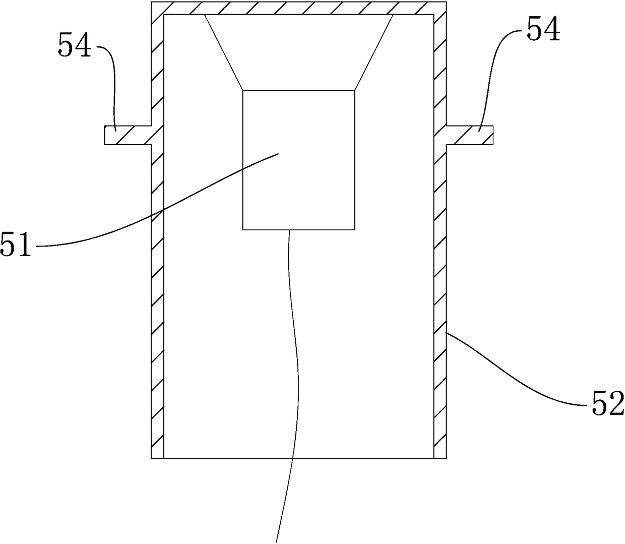
[0016] Such as Figure 1 to Figure 6 As shown, an ultrasonic electromagnetic cooking appliance according to the present invention includes a furnace shell 1, an electromagnetic coil 2, a drive circuit control board 3, a microcrystalline panel or a furnace seat 4, an ultrasonic generating mechanism 5, and a telescopic temperature measuring probe 6 and cooling fan 7, wherein, the microcrystalline panel or furnace seat 4 is installed on the top of the furnace shell 1, and the ultrasonic generating mechanism 5 includes an ultrasonic transducer 51, a casing 52, and a spring 53. The microcrystalline panel or the furnace seat 4 is provided with a mounting hole 41 for nesting of the casing 52, the ultrasonic transducer 51 is fixedly installed on the inner top surface of the casing 52, and the casing 52 is set in the mounting hole 41 , a limiter 54 is also provided on the outer surface of the casing 52, and the limiter 54 is stuck on the edge of the bottom surface of the installation h...


PUM


Abstract

The invention relates to an ultrasonic electromagnetic cooking tool which comprises a furnace shell, an electromagnetic coil, a driving circuit control panel, a microcrystalline panel or a furnace base, an ultrasonic generating mechanism, a telescopic temperature measuring probe and a cooling fan, the ultrasonic generating mechanism comprises an ultrasonic transducer, a sleeve shell, and a spring,the microcrystal panel or the furnace base is provided with a mounting hole, the ultrasonic transducer is fixedly arranged on the inner top surface of the sleeve shell, the sleeve shell is arranged in the mounting hole in a sleeved mode, a limiting part is further arranged on the outer surface of the sleeve shell, the limiting part is clamped on the bottom hole edge of the mounting hole; the lower end of the spring is installed in the furnace shell, the upper end of the spring abuts against the bottom of the sleeve shell, the upper portion of the sleeve shell is arranged on the surface of themicrocrystalline panel or the furnace base under the elastic action of the spring, so as to drive the ultrasonic transducer to vertically and movably extend out of the surface of the microcrystallinepanel or the furnace base; and the telescopic temperature measuring probe is arranged on a through hole formed in the microcrystalline panel or the furnace base.

Description

technical field [0001] The invention relates to the field of household appliances, in particular to an electromagnetic cooking appliance. Background technique [0002] Induction cooker, also known as induction cooker, is the product of the modern kitchen revolution. It produces an alternating magnetic field on the pot body, allowing heat to be generated directly at the bottom of the pot without open flame or conductive heating, and achieves the purpose of cooking food in the pot. It is a kind of thermal efficiency. Extremely high, high-efficiency and energy-saving stoves are completely different from all traditional fire or non-fire conduction heating stoves. However, no matter how high the thermal efficiency of the induction cooker is, before the food and liquid in the pot are heated to boiling, the food is basically deposited at the bottom of the pot. As the cooking time increases slowly, the food at the bottom of the pot will be slower than The food on the top is heated ...

Claims


Application Information

Patent Timeline
Patent Type & Authority Applications(China)
IPC IPC(8): H05B6/12H05B6/06A47J36/00A47J36/24
CPCA47J36/00A47J36/2483H05B6/062H05B6/12H05B6/1263
Inventor 彭志军
Owner 彭志军
Why Eureka
Try Eureka