Waste gas treatment device for fabric dyeing and finishing equipment

A waste gas treatment device, dyeing and finishing technology, applied in the direction of combination device, separation device, filter circuit, etc., can solve the problems of wasting water resources, water pollution, affecting the service life of the device, etc., to prevent pollution, save water resources, and realize recycling The effect of using

Inactive Publication Date: 2018-08-28
长兴瑞韬纺织科技有限公司
View PDF1 Cites 5 Cited by
  • Summary
  • Abstract
  • Description
  • Claims
  • Application Information

AI Technical Summary

Problems solved by technology

[0004] The purpose of the present invention is to provide a waste gas treatment device for fabric dyeing and finishing equipment, to solve the problem that the device proposed in the background technology cannot be filtered when the spray water is in operation, and it will be directly discharged to cause water pollution and waste water resources. When spraying, water is easy to adhere to the inner wall of the spraying chamber, which will easily cause scale and rust on the inner wall, which will affect the service life of the device

Method used


Image

  • Waste gas treatment device for fabric dyeing and finishing equipment
  • Waste gas treatment device for fabric dyeing and finishing equipment
  • Waste gas treatment device for fabric dyeing and finishing equipment

Examples


Embodiment Construction

[0019] The following will clearly and completely describe the technical solutions in the embodiments of the present invention with reference to the accompanying drawings in the embodiments of the present invention. Obviously, the described embodiments are only some, not all, embodiments of the present invention. Based on the embodiments of the present invention, all other embodiments obtained by persons of ordinary skill in the art without making creative efforts belong to the protection scope of the present invention.

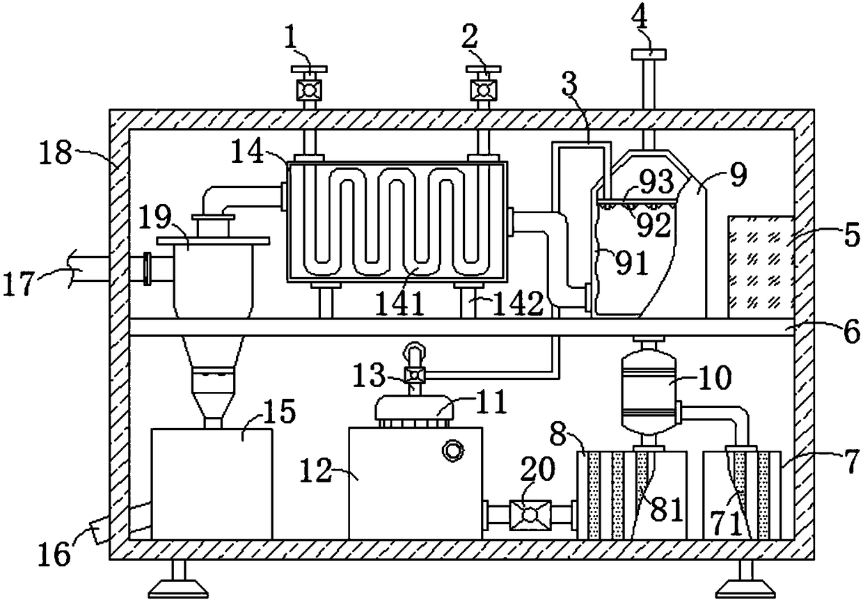
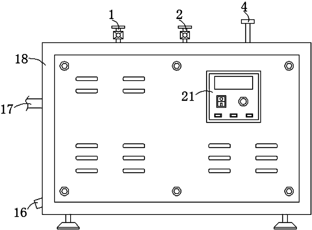
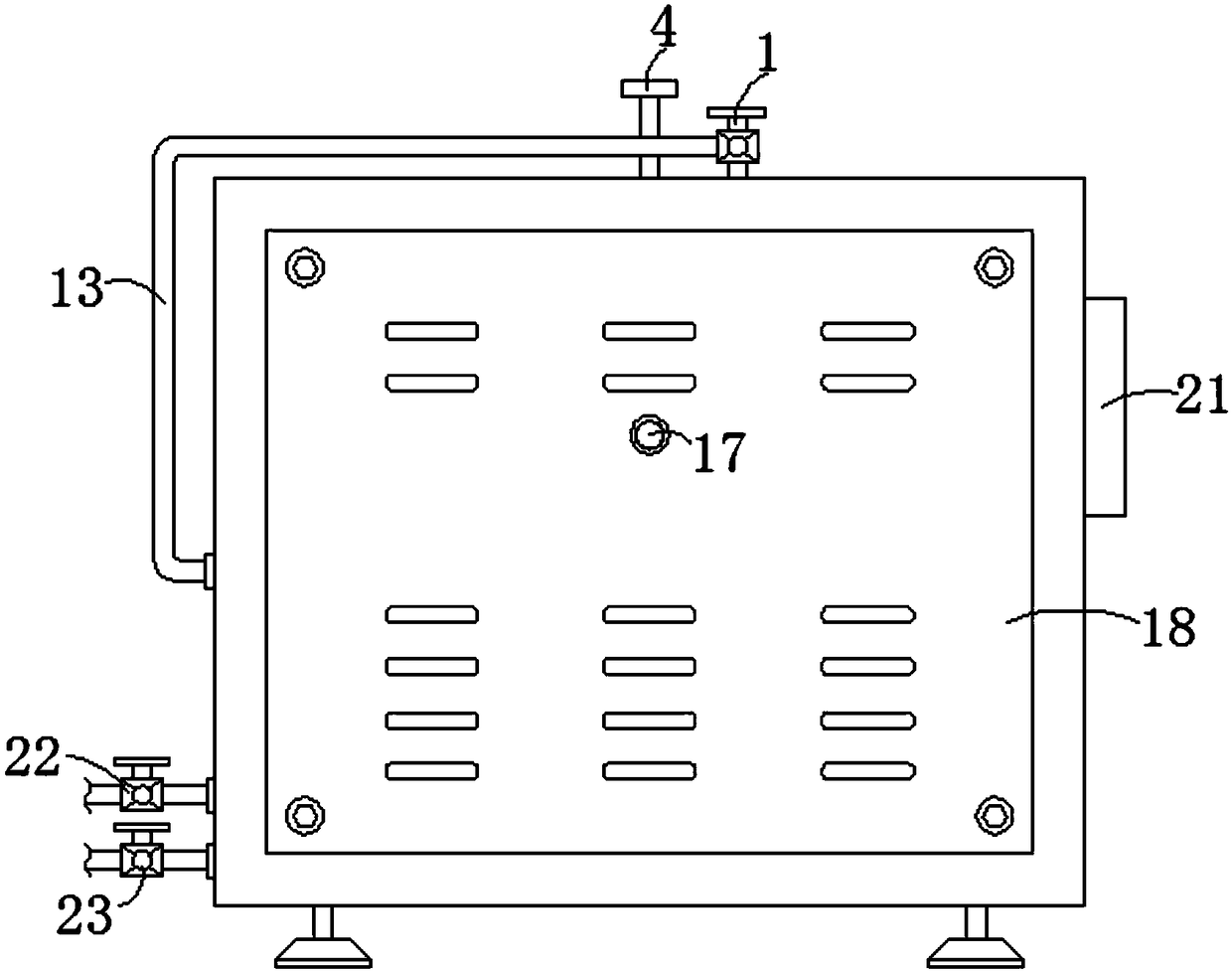
[0020] see Figure 1-3 , the present invention provides a technical solution: an exhaust gas treatment device for fabric dyeing and finishing equipment, including a cabinet body 18, a partition 6 is installed at the middle position inside the cabinet body 18, and a side of the upper surface of the partition 6 is installed with Cyclone separator 19, a controller 5 is installed on the upper surface of the dividing plate 6 relative to the side of the cyclone sepa...


PUM


Abstract

The invention discloses a waste gas treatment device for fabric dyeing and finishing equipment. The waste gas treatment device comprises a case body; a partition plate is mounted in a middle positioninside the case body, and a cyclone separator is mounted on one side of the upper surface of the partition plate; a controller is mounted on one side, relative to the cyclone separator, on the upper surface of the partition plate; a heat exchanger chamber is connected with one side of the cyclone separator through a pipeline; a dust collecting box is connected with the bottom end of the cyclone separator through the pipeline, and an air outlet pipe is connected with one side of the cyclone separator; a dust outlet is formed in one side of the dust collecting box. The waste gas treatment devicedisclosed by the invention has the benefits that a waste oil filter tank and a wastewater filter tank are arranged, so that the purification of wastewater and waste oil is realized, the recycling ofwater resources is realized, water resources are saved, and meanwhile, the pollution caused by the discharge of the waste oil is prevented, therefore, the waste gas treatment device is more environmentally friendly; as an arc-shaped inner wall is arranged, the water flow rate and the water flow state are changed, so that the fluidity of the oil and the water is improved, the generation of water scales on the inner wall is prevented, and the service life of the device is prolonged.

Description

technical field [0001] The invention belongs to the technical field of textile machinery, and in particular relates to a waste gas treatment device of fabric dyeing and finishing equipment. Background technique [0002] Textile machinery refers to the various machinery and equipment required to process natural fibers or chemical fibers into textiles. Textile machinery is usually classified according to the production process, mainly including spinning equipment, weaving equipment, printing and dyeing equipment, finishing equipment, chemical fiber spinning equipment, Silk reeling equipment and non-woven fabric equipment. [0003] In the Chinese patent with the patent number CN201510759848.7, an environment-friendly printing and dyeing setting machine exhaust gas purification treatment device is proposed. Through the set gravity settling chamber, heat exchange equipment, spray dust removal room and electrostatic precipitator, the exhaust gas Filtration of doped dust and fluff...

Claims


Application Information

Patent Timeline
Patent Type & Authority Applications(China)
IPC IPC(8): B01D50/00B01D36/00
CPCB01D36/006B01D2247/04B01D50/40
Inventor 李岩郭小冰杭鹏程
Owner 长兴瑞韬纺织科技有限公司
Why Eureka
Try Eureka