
Bearing machining equipment with waste material collection function

A technology for bearing processing and waste collection, which is applied to metal processing equipment, milling machine equipment, details of milling machine equipment, etc., and can solve problems such as lack of cooling collection devices

Inactive Publication Date: 2018-08-28
YANCHENG SANCHUAN BEARING MFG
View PDF0 Cites 3 Cited by
  • Summary
  • Abstract
  • Description
  • Claims
  • Application Information

AI Technical Summary

Problems solved by technology

[0003] The purpose of the present invention is to solve the problem of lack of cooling collection device in the waste collection in the prior art, and propose bearing processing equipment with waste collection function

Method used


Image

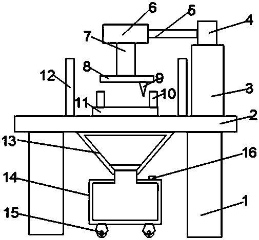
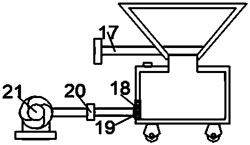
  • Bearing machining equipment with waste material collection function
  • Bearing machining equipment with waste material collection function

Examples


Embodiment Construction

[0015] The following will clearly and completely describe the technical solutions in the embodiments of the present invention with reference to the accompanying drawings in the embodiments of the present invention. Obviously, the described embodiments are only some of the embodiments of the present invention, not all of them.

[0016] In describing the present invention, it should be understood that the terms "upper", "lower", "front", "rear", "left", "right", "top", "bottom", "inner", " The orientation or positional relationship indicated by "outside", etc. is based on the orientation or positional relationship shown in the drawings, and is only for the convenience of describing the present invention and simplifying the description, rather than indicating or implying that the referred device or element must have a specific orientation, so as to Specific orientation configurations and operations, therefore, are not to be construed as limitations on the invention.

[0017] refe...


PUM


Abstract

The invention discloses bearing machining equipment with a waste material collection function. The bearing machining equipment comprises a supporting frame, wherein the upper end of the supporting frame is fixedly connected with a supporting table; a supporting rod is mounted at the right end of the supporting table; a rotating table is mounted at the upper end of the supporting rod; one end of the rotating table is connected with a cantilever; a variable-frequency speed adjuster is mounted at the end, which is far away from the rotating table, of the cantilever; the lower end of the variable-frequency speed adjuster is fixedly connected with a guide column; the lower end of the guide column is connected with a fixed block; a milling cutter is mounted at the lower end of the fixed block; two clamping blocks are symmetrically mounted below the milling cutter; the lower ends of the clamping blocks are connected with a fixed seat. The bearing machining equipment disclosed by the inventioncan resist scrap iron in a bearing machining process through a baffle plate, so as to prevent the scraps from injuring people; the scrap iron can be collected through a material feeding hopper and acooling tank; a fan can cool the scrap iron through a ventilating mesh; an air discharging pipe can be removed through an insertion slot, so that the scrap irons can be transported away more conveniently when being accumulated to a certain extent.

Description

technical field [0001] The invention relates to a bearing processing equipment with waste material collection function. Background technique [0002] Bearings are an important part of contemporary mechanical equipment. There are various types of bearings, which require various machine tools to process. The iron filings and steel purity produced during the machining of bearings by machine tools are relatively high. Most of the existing collection devices during bearing processing can collect the waste, but the heat of the waste after processing is high. If it is placed directly and transported away, it will easily cause burns to people. Some cooling equipment will undoubtedly add to the enterprise. A lot of cost. Contents of the invention [0003] The object of the present invention is to solve the problem of lack of cooling collection device in waste collection in the prior art, and propose a bearing processing equipment with waste collection function. [0004] In order...

Claims


Application Information

Patent Timeline
Patent Type & Authority Applications(China)
IPC IPC(8): B23C3/00B23Q11/08B23Q11/00
CPCB23C3/00B23Q11/0067B23Q11/08
Inventor 闫柯朱晨朱洪亮
Owner YANCHENG SANCHUAN BEARING MFG
Learn More