Parts Packaging Transfer Equipment

A transmission equipment and packaging technology, which is applied in the field of parts processing, can solve the problems of small screw size, straightening, and reduce the installation efficiency of the device, so as to achieve the effect of synchronous installation

Active Publication Date: 2020-03-31
CHONGQING IND POLYTECHNIC COLLEGE
View PDF4 Cites 0 Cited by
  • Summary
  • Abstract
  • Description
  • Claims
  • Application Information

AI Technical Summary

Problems solved by technology

After the screw processing is completed, the screws will be packaged. The common packaging method is to place the screws in the packaging bag in an orderly manner. It is difficult to count the screws, and it is easy to cause errors between the number of screws in the package and the specified quantity; The screws in the bag are in a disordered state. When using the screws in the packaging bag, the screws need to be extracted
[0003] When installing the extracted screws, it is necessary to face the lower end of the screw to the mounting hole first, and then install the screws. Most of the screws are small in size, and it is difficult to straighten them by hand, which makes it difficult to use the screws and reduces the It is difficult to install the device or reduce the installation efficiency of the device

Method used


Image

  • Parts Packaging Transfer Equipment
  • Parts Packaging Transfer Equipment
  • Parts Packaging Transfer Equipment

Examples


Embodiment Construction

[0019] Further detailed explanation through specific implementation mode below:

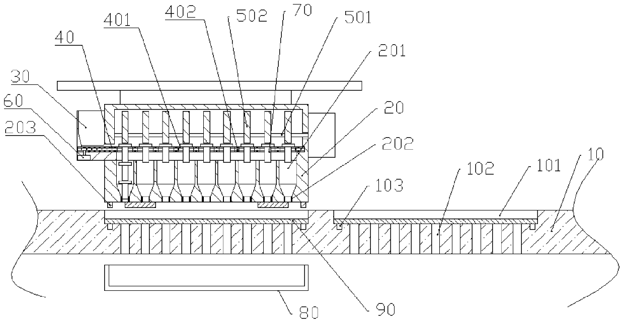
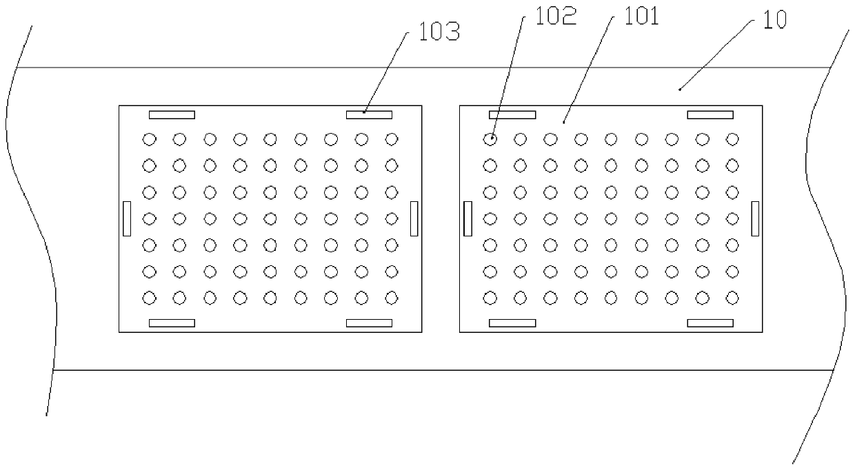
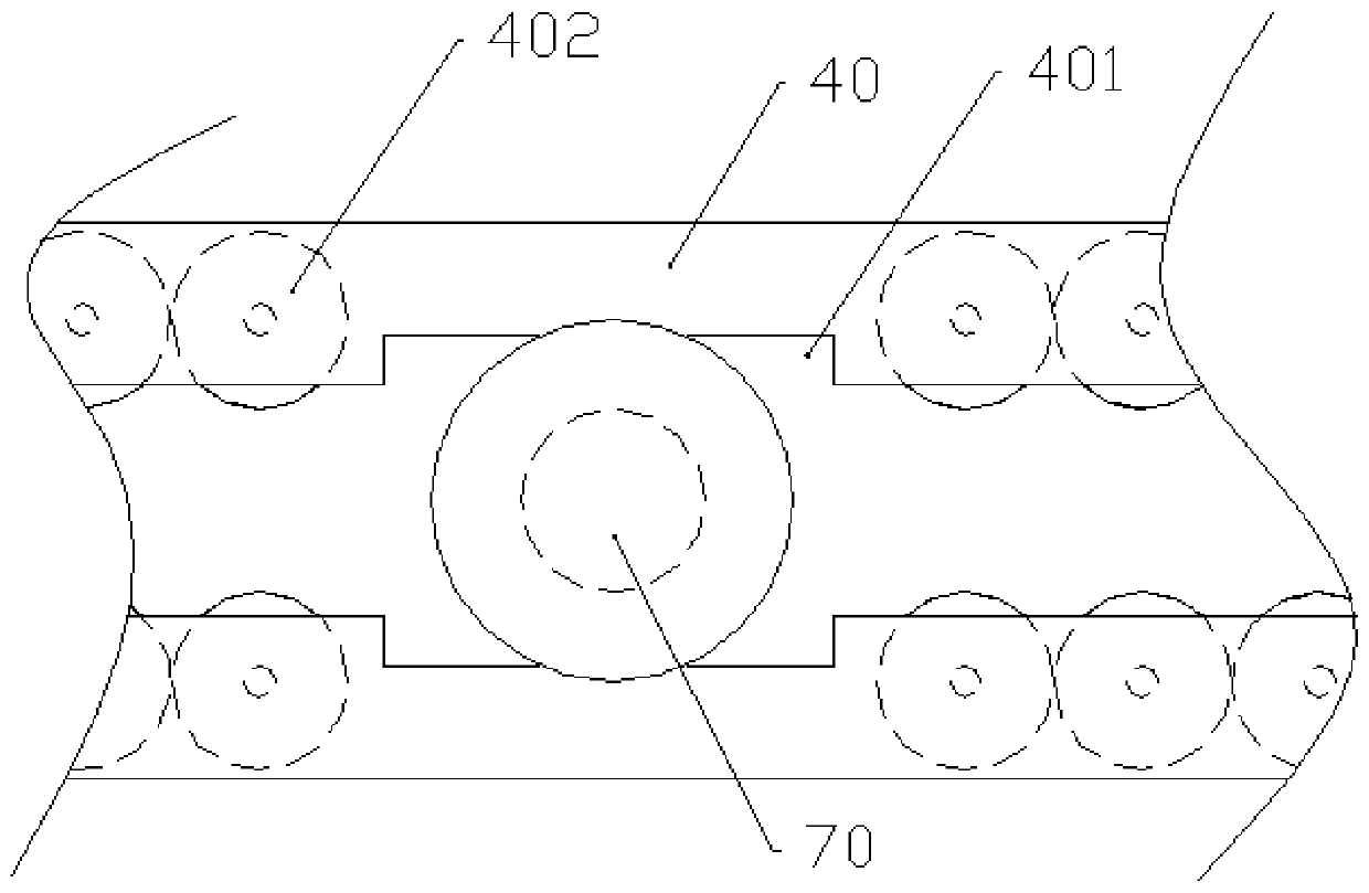
[0020] The reference numerals in the accompanying drawings of the description include: conveyor belt 10, transmission trough 101, first through hole 102, groove 103, installation box 20, second through hole 201, first heating wire 202, second heating wire 203, Feed chute 30, support belt 40, drop chute 401, transmission wheel 402, rotating rod 501, cam 502, micromotor 60, screw 70, collecting tank 80, plastic plate 90.

[0021] The embodiment is basically as attached figure 1 , attached figure 2 And attached image 3 Shown: Parts packaging and conveying equipment, including an arrangement mechanism, a micro motor 60, and a conveyor belt 10 for horizontal transmission. The conveyor belt 10 is provided with a conveying groove 101 for placing a plastic plate 90, and the conveying groove 101 is provided with several vertical first through holes. 102.

[0022] The alignment mechanism includes an ...


PUM


Abstract

The invention relates to the field of part machining and particularly discloses part packaging and conveying equipment. The part packaging and conveying equipment comprises a conveyor belt, a mountingbox, a feed chute, a plurality of conveying wheels, supporting belts, a rotary rod and cams. The conveyor belt is provided with conveying grooves. Each conveying groove is internally provided with first through holes. The supporting belts are arranged oppositely and horizontally fixed to the interior of the mounting box. One end of each supporting belt is located in the feed chute. The distance between the adjacent supporting belts is consistent with the diameter of a thread of each screw. The supporting belts are provided with opposite falling slots. The conveying wheels are uprightly and rotatably mounted in the supporting belts. The two adjacent conveying wheels make contact with each other. Moreover, the conveying wheels make contact with the threads of the corresponding screws. The lower surface of the mounting box is provided with a plurality of second through holes. The first through holes, the corresponding falling slots and the corresponding second through holes are located on the same vertical axes. The rotary rod is mounted in the mounting box. The cams are coaxially mounted on the rotary rod. The side faces f the cams make contact with the tops of the corresponding screws. The part packaging and conveying equipment can be used for arranging and packaging the screws.

Description

technical field [0001] The invention belongs to the field of parts processing, and in particular relates to parts packaging and conveying equipment. Background technique [0002] A screw is a common fastener, generally made of metal or plastic, cylindrical in shape, and grooves engraved with concave and convex on the surface are called threads. After the screw processing is completed, the screws will be packaged. The common packaging method is to place the screws in the packaging bag in an orderly manner. It is difficult to count the screws, and it is easy to cause errors between the number of screws in the package and the specified quantity; The screws in the bag are in a disordered state. When using the screws in the packaging bag, the screws need to be extracted. [0003] When installing the extracted screws, it is necessary to face the lower end of the screw with the installation hole first, and then install the screws. Most of the screws are small in size, and it is di...

Claims


Application Information

Patent Timeline
Patent Type & Authority Patents(China)
IPC IPC(8): B65B35/02B65B35/44B65G15/58
CPCB65B35/02B65B35/44B65G15/58B65G2201/0217
Inventor 朋宇姚雪儒黄月何明何婉亭欧阳婧芸
Owner CHONGQING IND POLYTECHNIC COLLEGE
Why Eureka
Try Eureka