Elevator speed limiter capable of following up with elevator car

An elevator speed limiter and follow-up technology, applied in the elevator safety and elevator fields, can solve the problems of long installation and debugging time, high speed when the car stops, and safety gear trigger delay, etc., to save installation and debugging time, solve the The effect of occupying shaft space and shortening the trigger time

Pending Publication Date: 2018-08-28
南通中力科技有限公司
View PDF5 Cites 6 Cited by
  • Summary
  • Abstract
  • Description
  • Claims
  • Application Information

AI Technical Summary

Problems solved by technology

Defects of this method: First, the drive chain (wire rope) between the speed limiter and the safety gear is too long, which leads to a delay in the triggering of the safety gear, so that the speed of the car is too high when it is stopped, resulting in a large impact, and even The brake may fail; the second is that the speed limiter and its tensioning device need to occupy the well space separately, which reduces the utilization rate of the well space; the third is that the connection between the speed limiter and the safety gear lifting mechanism needs to be completed on site, and the on-site installation and commissioning time relatively long

Method used


Image

  • Elevator speed limiter capable of following up with elevator car
  • Elevator speed limiter capable of following up with elevator car
  • Elevator speed limiter capable of following up with elevator car

Examples


Embodiment Construction

[0015] The application will be further described in detail below in conjunction with the accompanying drawings and embodiments. It should be understood that the specific embodiments described here are only used to explain related inventions, rather than to limit the invention. It should also be noted that, for ease of description, only parts related to the invention are shown in the drawings.

[0016] It should be noted that, in the case of no conflict, the embodiments in the present application and the features in the embodiments can be combined with each other. The present application will be described in detail below with reference to the accompanying drawings and embodiments.

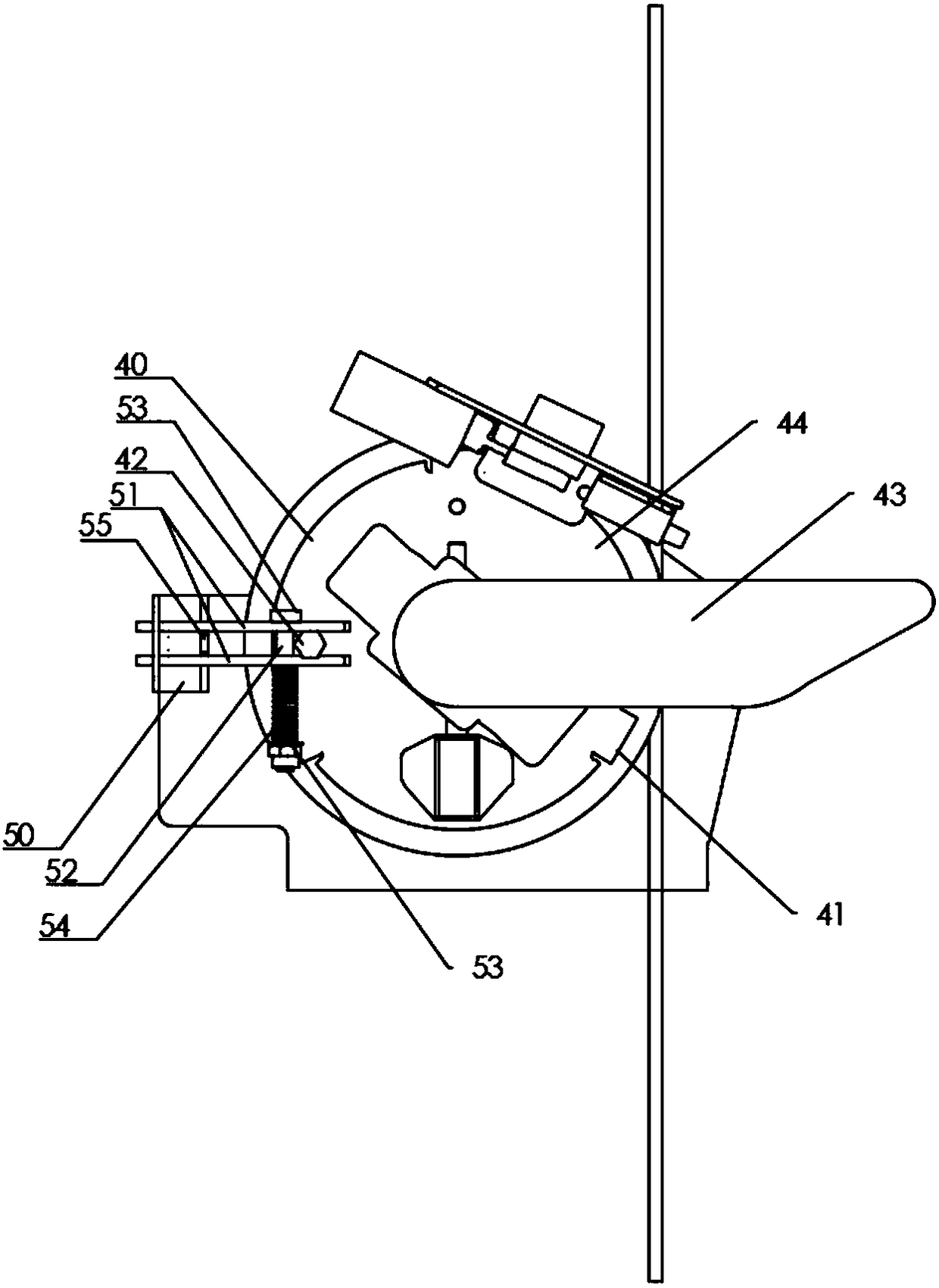
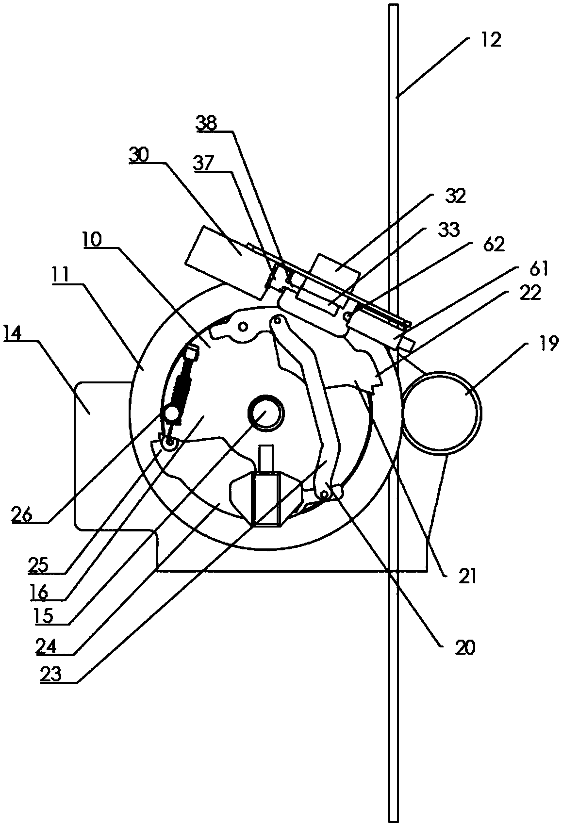
[0017] One of the embodiments of the present invention is, please refer to figure 1 and 2 , the car follow-up elevator speed governor of the present invention includes a rotating device 10 and at least one action mechanism 20,

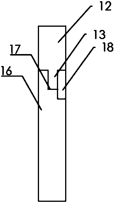
[0018] The rotating device 10 is provided with a driving wheel 12, ...


PUM


Abstract

The invention discloses an elevator speed limiter capable of following up with an elevator car. The elevator speed limiter comprises a rotating device and at least one three-connecting-rod mechanism,and further comprises an electrical triggering device and a mechanical triggering device, wherein the three-connecting-rod mechanism is equipped with a first connecting rod, a second connecting rod and a third connecting rod which are connected in sequence; both the first connecting rod and the third connecting rod are rotationally connected with the rotating device; the first connecting rod and/or the third connecting rod are/is connected with the rotating device through a first spring; the rotating device is equipped with a driving wheel; the driving wheel is driven by a synchronous belt ora steel wire rope which is arranged along the vertical direction; both ends of the synchronous belt and the steel wire rope are correspondingly fixed at the top and the bottom of an elevator shaft; the electrical triggering device is equipped with a first triggering stop block; the mechanical triggering device is equipped with a second triggering stop block; and both the first triggering stop block and the second triggering stop block are arranged on a rotating path formed after the radial displacement of the first connecting rod and/or the third connecting rod along the rotating device. Consequently, the safety gear triggering time is shortened, the elevator shaft space utilization ratio is improved, and the onsite mounting and debugging time is saved.

Description

technical field [0001] The present disclosure generally relates to the field of elevators, specifically to the field of elevator safety, and in particular to a car-following elevator speed governor. Background technique [0002] The elevator speed limiter is one of the four major safety components of the elevator. It is to ensure that the elevator can trigger the safety device action in time in the case of accidental overspeed, so as to stop the elevator and ensure the safety of the life and property of the elevator passengers. [0003] The traditional speed limiter is installed on the top of the elevator machine room or shaft, and the safety gear is installed on the elevator car. Defects of this method: First, the drive chain (wire rope) between the speed limiter and the safety gear is too long, which leads to a delay in the triggering of the safety gear, so that the speed of the car is too high when it is stopped, resulting in a large impact, and even The brake may fail;...

Claims


Application Information

Patent Timeline
Patent Type & Authority Applications(China)
IPC IPC(8): B66B5/04
CPCB66B5/044B66B5/048
Inventor 金锋夏学涛戎世文范伟金桂勇秦锦华
Owner 南通中力科技有限公司
Why Eureka
Try Eureka