
Self-calibration detection device and temperature demodulation method oriented to optical fiber Raman temperature sensing system

A sensing system and detection device technology, applied in the field of temperature demodulation, can solve the problems of system temperature measurement performance decline, fiber sudden bending, etc. Effects of low temperature accuracy

Active Publication Date: 2018-08-28
TAIYUAN UNIV OF TECH
View PDF6 Cites 6 Cited by
  • Summary
  • Abstract
  • Description
  • Claims
  • Application Information

AI Technical Summary

Problems solved by technology

[0005] In order to solve the problem that the temperature measurement performance of the existing distributed optical fiber Raman sensing system drops sharply due to phenomena such as optical fiber dispersion, APD temperature drift, and optical fiber sudden bending, the present invention proposes a distributed optical fiber Raman temperature sensor System self-calibration detection device and temperature demodulation method

Method used


Image

  • Self-calibration detection device and temperature demodulation method oriented to optical fiber Raman temperature sensing system
  • Self-calibration detection device and temperature demodulation method oriented to optical fiber Raman temperature sensing system
  • Self-calibration detection device and temperature demodulation method oriented to optical fiber Raman temperature sensing system

Examples


Embodiment Construction

[0046] Specific embodiments of the present invention will be described in detail below in conjunction with the accompanying drawings.

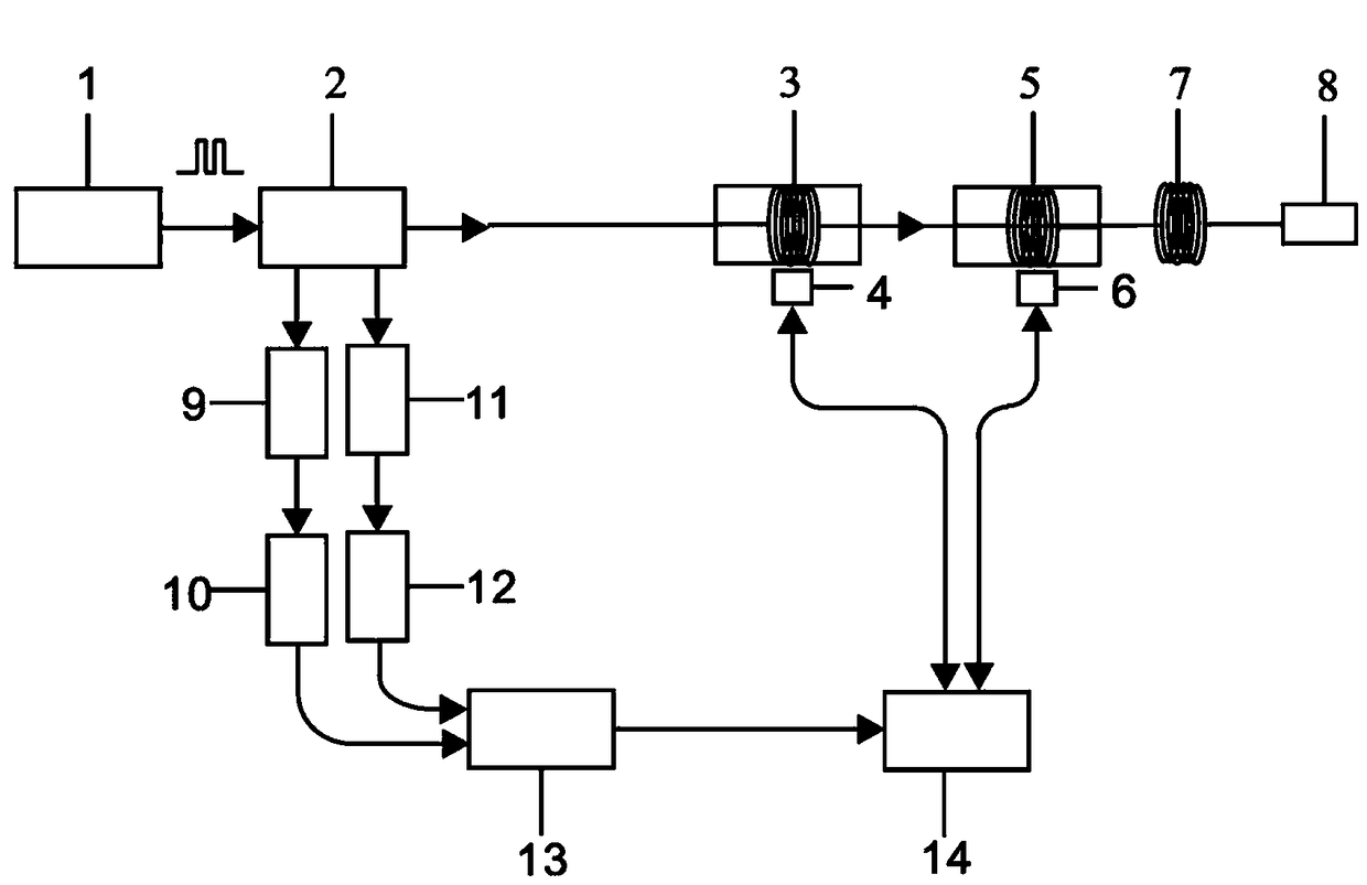
[0047] A temperature demodulation method for optical fiber Raman sensing system is realized by the following self-calibration temperature detection device. The device includes 1550nm pulsed laser, wavelength division multiplexer (WDM), 2 avalanche photodiodes (APD), 2 low noise amplifiers (LNA), multimode sensing fiber (ordinary multimode fiber), data acquisition card, Computer, 2 sections of reference fiber loops, 2 constant temperature baths (for placing the first reference fiber loop and the second reference fiber loop) and 1 multimode fiber optic mirror.

[0048] A temperature demodulation method for optical fiber Raman sensing system is divided into the following four steps.

[0049] Step 1. Build a self-calibrating temperature detection device for optical fiber Raman sensing system;

[0050] The self-calibrating temperature detection d...


PUM

PropertyMeasurementUnit
Wavelengthaaaaaaaaaa
Pulse widthaaaaaaaaaa

Abstract

The invention discloses a self-calibration detection device and a temperature demodulation method oriented to an optical fiber Raman temperature sensing system. The self-calibration detection device comprises an optical fiber Raman thermodetector, a constant temperature tank, a multi-mode sensing fiber and a multi-mode reflector, wherein the optical fiber Raman thermodetector comprises a pulse laser; the output end of the pulse laser is connected with the input end of WDM (Wavelength Division Multiplex); two output ends of the WDM are respectively connected with the input ends of a first APD (Angular Position Digitizer) and a second APD; the output end of the first APD is connected with the input end of a first LNA (Low Noise Amplifier); the output end of the second APD is connected with the input end of the second LNA; the output end of the first LNA and the output end of the second LNA are connected with the input end of a data acquisition card; the output end of the data acquisitioncard is connected with the input end of a computer. According to the self-calibration detection device, the problems of low temperature measuring accuracy, lower temperature measurement stability andlow temperature measurement efficiency caused by a temperature demodulation method in an existing distributed optical fiber Raman temperature measuring system can be solved.

Description

technical field [0001] The invention relates to the field of temperature demodulation in a distributed optical fiber sensing system, in particular to a self-calibrating temperature detection device and a temperature demodulation method for an optical fiber Raman sensing system. Background technique [0002] Distributed optical fiber sensing technology uses the optical fiber itself as both a signal transmission medium and a sensing unit to obtain the distribution of external physical quantities of the entire optical fiber link. The distributed optical fiber sensing system has high measurement accuracy, long sensing distance, and good reliability. It has been widely used in the health monitoring of infrastructure such as smart grids. [0003] In the distributed optical fiber Raman temperature measurement system, the commonly used temperature demodulation method is to use Stokes backscattered light as the reference channel, use anti-Stokes backscattered light as the signal chan...

Claims


Application Information

Patent Timeline
IPC IPC(8): G01K15/00G01K11/32G01K11/324
CPCG01K11/32G01K15/005G01K15/007G01K11/324
Inventor 张明江李健张建忠乔丽君闫宝强许扬靳宝全王东王宇王云才
Owner TAIYUAN UNIV OF TECH
Learn More