Device for testing electrical performances of diode

An electrical performance test and diode technology, applied in the field of diode detection devices, can solve problems such as current limitation, chip diode damage, damage, etc., to achieve the effects of improving current bearing capacity, increasing test area, and optimizing test points

Inactive Publication Date: 2018-08-28
NANTONG HORNBY ELECTRONICS
View PDF6 Cites 4 Cited by
  • Summary
  • Abstract
  • Description
  • Claims
  • Application Information

AI Technical Summary

Problems solved by technology

[0003] In the prior art, manufacturers will carry out sampling tests on SMD LEDs. The general testing process is to clamp the SMD diodes, and then connect them to a diode electrical tester for detection of SMD diodes; however, the above The test process has great defects: the continuous clamping or loosening will cause damage to the SMD diode, and the clamping part will be damaged after repeated use, which will affect the use
[0004] Further entered into the patent number: CN 205880139 U, a patch diode test device, which is easy to operate and has high test efficiency, but the test point uses a Φ1.5mm copper needle, which has the problems of small contact area and limited current. When testing with a current greater than 30A, there is a risk of ignition of the diode, which may easily cause the diode to be broken down and damaged

Method used


Image

  • Device for testing electrical performances of diode
  • Device for testing electrical performances of diode
  • Device for testing electrical performances of diode

Examples


Embodiment Construction

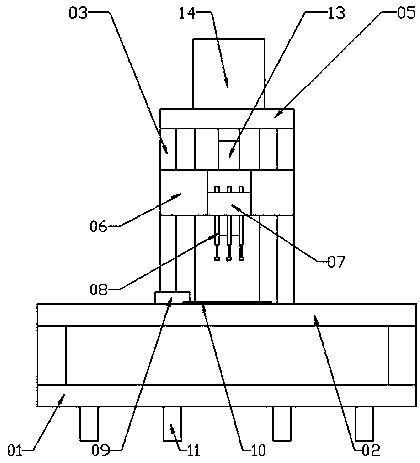
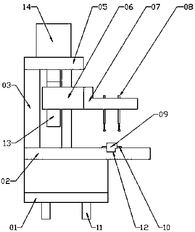
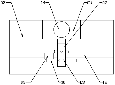
[0018] Refer to attached Figure 1-3 , a diode electrical performance testing device, which includes a bracket 03, a substrate 02, and a base 01; the base 01 is provided with a substrate 02, one side of the substrate 02 is provided with a bracket 03, and one side of the bracket 03 is provided with two slide bars 04, the sliding rod 04 is set at intervals, the top of the sliding rod 04 is fixed on the bracket through the horizontal plate 05, the sliding block 06 is installed on the sliding rod 04, the measuring block 07 is set on one side of the sliding block 06, and three test blocks are set under the measuring block 07 needle 08, the other side of the substrate 02 is horizontally provided with a trough 12, the trough 12 runs through the substrate 02, and three test copper sheets 10 are respectively arranged on both sides of the trough 12, and there is a one-to-one correspondence between the test copper sheet 10 and the test needle 08, and As the test needle 08 moves up and do...


PUM


Abstract

The invention relates to a device for testing electrical performances of a diode. The device comprises a bracket, a substrate and a pedestal. A base plate is arranged on the pedestal; the bracket is arranged at one side of the base plate; two sliding rods are arranged at one side of the bracket at an interval; and the tops of the sliding rods are fixed at the bracket by a horizontal plate. A sliding block is installed on the sliding rods; a measuring block is arranged at one side of the sliding block; three testing pins are arranged below the measuring block; a trough is formed at the other side of the base plate horizontally and penetrates the base plate; and three copper testing pieces are arranged at the two sides of the trough, wherein the copper testing pieces correspond to the testing pins one by one. A plurality of plugs are arranged at the bottom of the pedestal and are connected with the testing pins and the copper testing pieces; and the plugs are connected with a diode electrical performance testing instrument in a pluggable manner. The testing device has advantages of reasonable design and simple structure; the testing points are optimized; with a ceramic-based copper-clad plate, the testing area is increased and the current bearing capacity is enhanced substantially; and when testing is carried out by using 60-A currents, no risk is caused.

Description

technical field [0001] The invention relates to the technical field of diode detection devices, in particular to a device for testing electrical properties of diodes. Background technique [0002] SMD LED is a new type of surface-mounted semiconductor light-emitting device. It has the advantages of small size, large scattering angle, good uniformity of light emission, and high reliability. It is widely used in electronic components that require signal indication and lighting. [0003] In the prior art, manufacturers will carry out sampling tests on SMD LEDs. The general testing process is to clamp the SMD diodes, and then connect them to a diode electrical tester for detection of SMD diodes; however, the above The testing process has great defects: continuous clamping or loosening will cause damage to the SMD diode, and the clamped part will be damaged after repeated use, which will affect the use. [0004] Further entered into the patent number: CN 205880139 U, a patch dio...

Claims


Application Information

Patent Timeline
Patent Type & Authority Applications(China)
IPC IPC(8): G01R31/26
CPCG01R31/26
Inventor 石友玲徐柏林阚俊丽
Owner NANTONG HORNBY ELECTRONICS
Why Eureka
Try Eureka