Vertical silos for dry storage of spent fuel in nuclear power plants

A technology for spent fuel and nuclear power plants, applied in the field of dry storage of spent fuel, which can solve problems such as being easily blocked by foreign objects, insufficient natural ventilation heat transfer, easy to overturn, etc., to avoid external attacks and damage, and eliminate hidden dangers of physical security Effect

Active Publication Date: 2021-08-24
中广核工程有限公司 +1
View PDF6 Cites 1 Cited by
  • Summary
  • Abstract
  • Description
  • Claims
  • Application Information

AI Technical Summary

Problems solved by technology

[0005] 1) The air inlet is located at the bottom, which is easy to be blocked, which affects the thermal safety of the equipment and the sealing safety of the spent fuel in the storage tank. Due to the low position of the air inlet, it is easy to be attacked by the outside, which poses a safety hazard;
[0006] 2) The vents are all open to the outside world without shelter, and are easily blocked by foreign matter, which affects the ventilation performance;
[0007] 3) Insufficient natural ventilation heat transfer affects the spent fuel loading performance of equipment;
[0008] 4) The radioactive dose level in the air inlet area at the bottom of the silo is relatively high, which affects the safety of personnel radiation shielding;
[0009] 5) The storage tank is unconstrained, and the silo is easy to tip over under accident conditions, which affects the safety of the equipment structure

Method used


Image

  • Vertical silos for dry storage of spent fuel in nuclear power plants
  • Vertical silos for dry storage of spent fuel in nuclear power plants
  • Vertical silos for dry storage of spent fuel in nuclear power plants

Examples


Embodiment 1

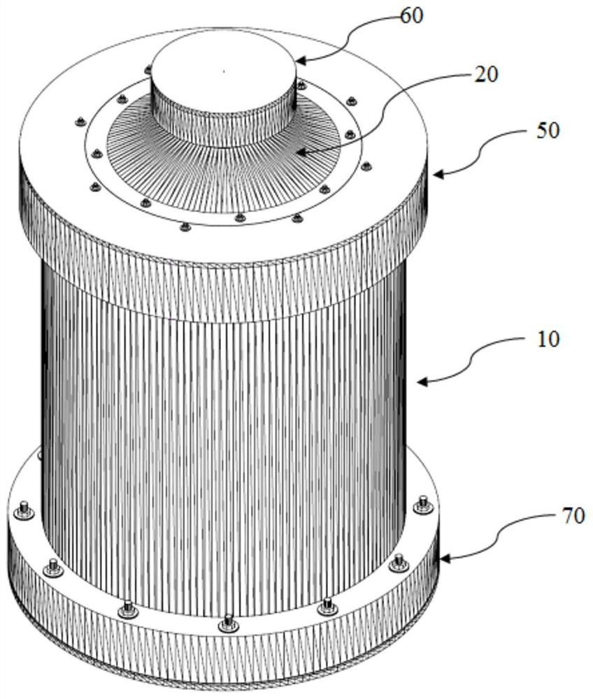
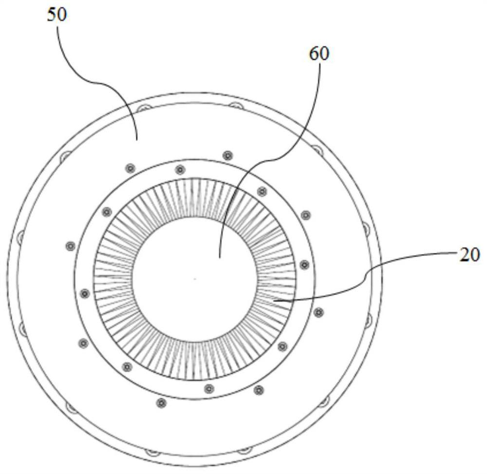
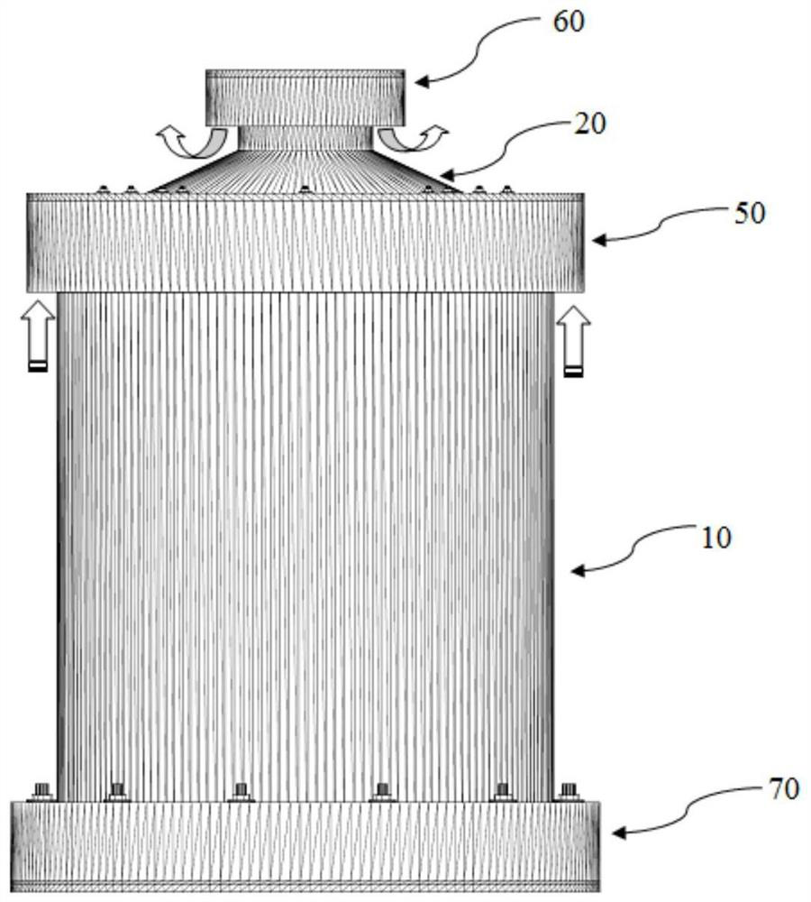
[0059] see Figure 1 to Figure 23 As shown, the vertical silo for dry storage of nuclear power plant spent fuel in the present invention includes a silo 10, a top cover 20 and a bottom plate 30, wherein the silo 10 includes an inner silo 100 and an outer silo 102, and the inner silo 100 There is a first annular cavity 104 between the outer silo 102 and the spent fuel storage tank 40 stored in the silo 10, and there is a second annular cavity 106 between the inner silo 100 and the spent fuel storage tank 40. The inner silo Between the bottom of 100 and the bottom plate 30, there is also an air inlet air channel 108 communicating with the first annular chamber 104 and the second annular chamber 106; the upper area of ​​the silo 10 is provided with an air inlet 110 communicating with the first annular chamber 104, The air inlet 110 is provided with an air inlet protective cover 50, the top cover 20 is provided with an air outlet 200, the air outlet 200 is provided with an air out...

Embodiment approach

[0075] see Figure 20 to Figure 22 As shown, as a preferred embodiment of the present invention, the vertical silo for nuclear power plant spent fuel storage of the present invention further includes a shielding ring 70 arranged at the outer bottom area of ​​the outer silo 102 . The shielding ring 70 is an integral concrete structure and is installed at the outer bottom end of the shell 1020 of the outer silo 102 . The shielding ring 70 is provided with 12 through fixing holes 700. After being inserted into the fixing screw 300 on the bottom plate 30, the shielding ring 70 is directly seated on the skirt 1024 of the external silo 102, and then fixedly connected with matching nuts, so that The shielding ring 70, the outer silo 102 and the inner silo 100 form an integral structural unit.

[0076] Since the circular air inlet air channel 108 between the bottom of the inner silo 100 and the bottom plate 30 adopts an unshielded full-range ventilation design, for the bottom area, o...

Embodiment 2

[0091] see Figure 24As shown, it is a schematic diagram of the second embodiment of the vertical silo for dry storage of nuclear power plant spent fuel in the present invention. The bottom of the cylinder 1000 is evenly spaced with a plurality of through holes 1000a, and the plurality of through holes 1000a constitute the air inlet air channel between the bottom of the inner silo 100 and the bottom plate 30.

[0092] The inner wall of the cylinder 1000 is provided with a steel lining 1004, and a vertical rib 1002 is welded on the steel lining 1004. The bottom of the vertical rib 1002 extends to the bottom plate 30 and is fixed by welding with the bottom plate 30. The top interface of the vertical rib 1002 Below the top interface of the cylinder 1000 , when the top cover (not shown in the figure) is used for sealing, the bottom of the top cover is nested inside the cylinder 1000 and supported on the top of the vertical rib 1002 .


PUM


Abstract

The invention discloses a vertical silo for dry storage of spent fuel in a nuclear power plant, which includes a silo, a top cover and a bottom plate, wherein the silo includes an inner silo and an outer silo, and the space between the inner silo and the outer silo is It has a first annular chamber, and when the spent fuel storage tank is stored in the silo, there is a second annular chamber between the inner silo and the spent fuel storage tank, and there is also a second annular chamber between the bottom of the inner silo and the bottom plate, which is connected with the first annular chamber and the spent fuel storage tank. The air flow channel of the air inlet connected to the second ring cavity; the upper area of ​​the silo is provided with an air inlet connected to the first ring cavity, the air inlet is provided with an air inlet protective cover, and the upper part of the top cover is provided with an air outlet. An air outlet protective cover is provided, the bottom of the silo is fixedly connected with the bottom plate, and the top cover is fixed on the upper part of the silo. Compared with the prior art, the vertical silo for dry storage of nuclear power plant spent fuel of the present invention can prevent the clogging of the ventilation opening, has high natural ventilation flow rate, good radiation shielding effect and safe overall structure.

Description

technical field [0001] The invention belongs to the field of dry storage of spent fuel discharged from nuclear power plant reactor cores, and more specifically relates to a vertical silo for dry storage of spent fuel in nuclear power plants. Background technique [0002] Vertical silos for dry storage of spent fuel (hereinafter referred to as "vertical silos") are mainly used to store and protect fuel storage tanks that contain sealed spent fuel assemblies. As important items for nuclear safety, vertical silos are used for long-term storage The main functions in the process include: 1) providing structural protection and radiation shielding for spent fuel storage tanks; 2) providing air convection channels, using natural air circulation to take away the decay heat of spent fuel components, so that spent fuel storage tanks can be fully cooled. [0003] At present, the vertical silo structure that is widely and maturely used in the world is generally an integrated vertical cyl...

Claims


Application Information

Patent Timeline
Patent Type & Authority Patents(China)
IPC IPC(8): G21F5/008G21F5/10G21F5/02
CPCG21F5/008G21F5/02G21F5/10
Inventor 程呈张学岭唐琼辉杨寿海
Owner 中广核工程有限公司
Why Eureka
Try Eureka