Array substrate and display device

An array substrate and display area technology, applied in semiconductor devices, electrical components, circuits, etc., can solve problems such as affecting display quality and increasing wiring resistance, so as to improve display quality, reduce overlap resistance, and avoid cathode overlap. effect of area

Active Publication Date: 2018-08-28
BOE TECH GRP CO LTD +1
View PDF11 Cites 21 Cited by
  • Summary
  • Abstract
  • Description
  • Claims
  • Application Information

AI Technical Summary

Problems solved by technology

However, as the line width of the line connected to the VSS power supply shrinks, the resistance of the line increases, which affects the display quality.

Method used


Image

  • Array substrate and display device
  • Array substrate and display device
  • Array substrate and display device

Examples


Embodiment 1

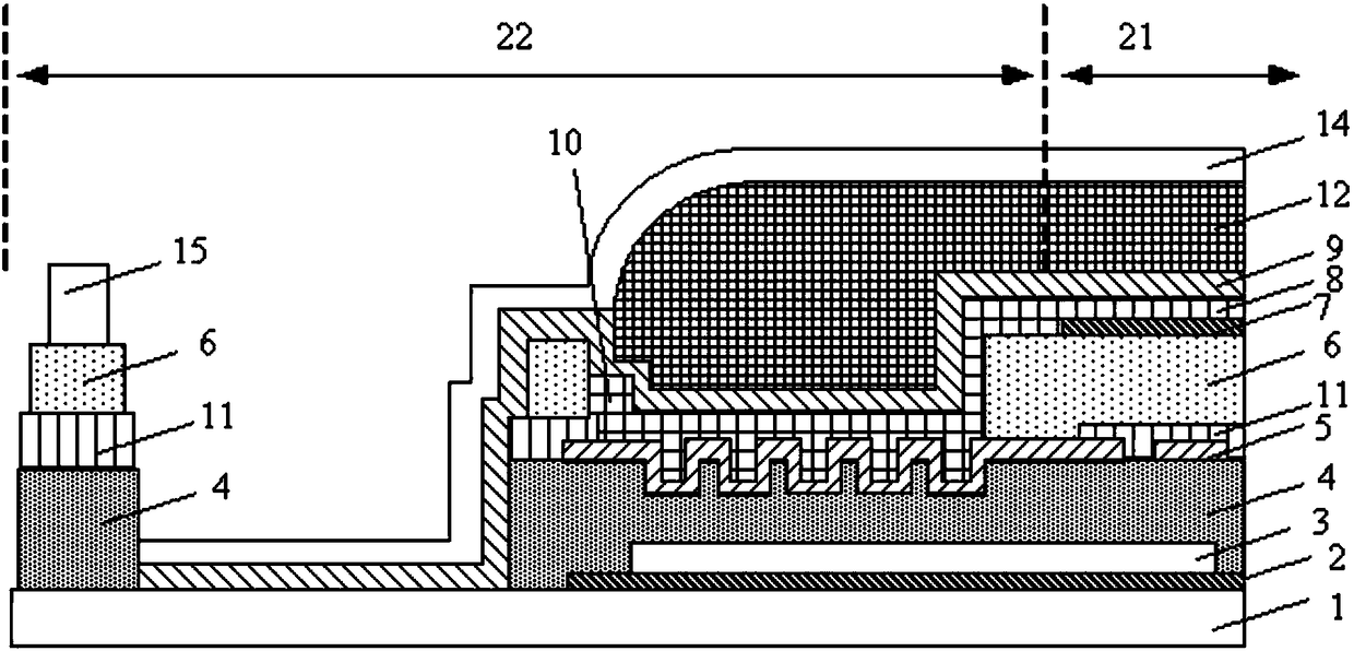
[0034] This embodiment aims at the problem that the narrow frame design compresses the overlapping area of ​​the cathode and the connecting wiring in the edge area, resulting in a decrease in display quality, and provides an array substrate. The overlap is set as a concave-convex zigzag surface connection to obtain a better narrow-frame cathode overlap structure, so that when the width of the cathode and the connecting trace is constant, the overlap area between the cathode and the connecting trace is guaranteed and the lap resistance is reduced. to improve display quality.

[0035] Such as figure 1 As shown, the array substrate includes a display area 21 and a non-display area 22 located on the periphery of the display area 21. The display area 21 includes a plurality of pixel structures, and the lead-out lines 10 of the pixel structures are overlapped with the connecting wires 5, and the connecting wires 5 are used for In the receiving signal supply circuit (located in fig...

Embodiment 2

[0050] This embodiment provides an array substrate, which can ensure the overlapped area of ​​the cathode and the connecting wires under the condition that the widths of the lead-out wires of the cathode and the connecting wires are constant, so as to improve the display quality.

[0051] Different from Embodiment 1, the array substrate in this embodiment is also provided with the same layer as the anode and the auxiliary connection line formed of the same material as the anode.

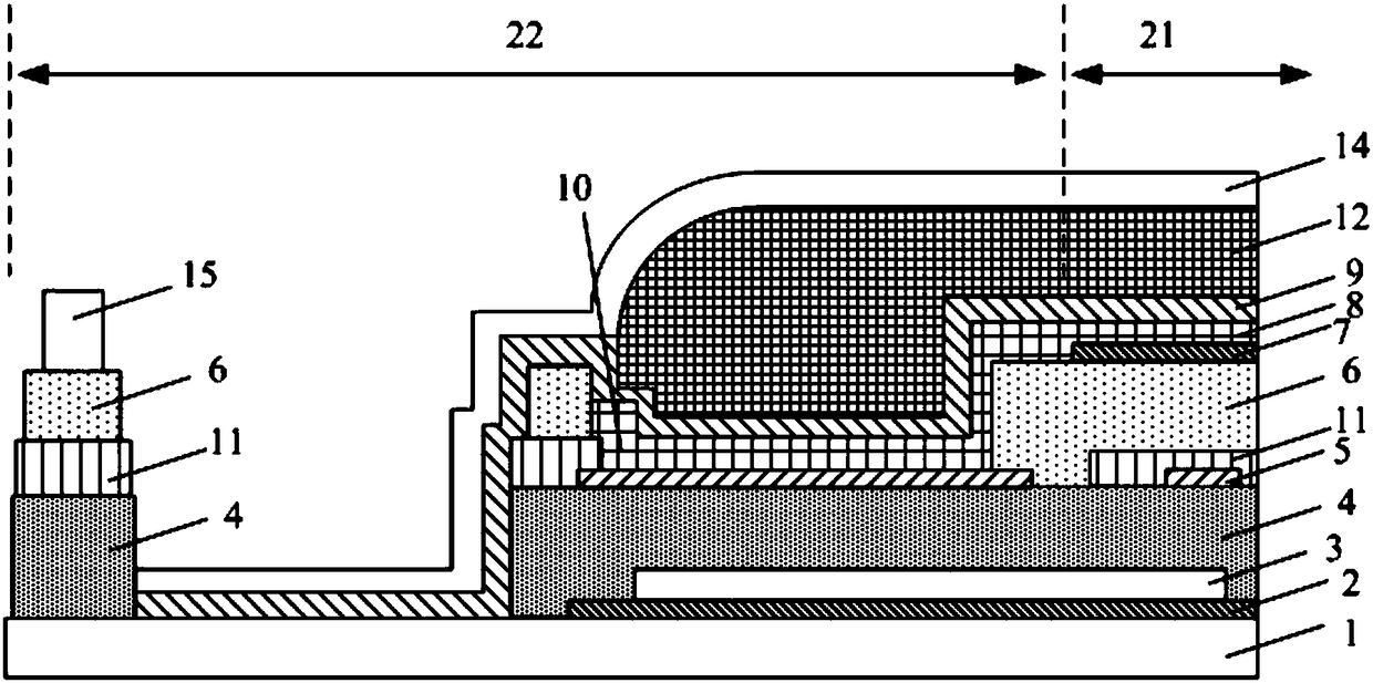
[0052] Such as Figure 4 As shown, in the area where the connecting wire 5 and the lead-out wire 10 overlap, an auxiliary connecting wire 13 is provided between the connecting wire 5 and the lead-out wire 10 , and the auxiliary connecting wire 13 is in direct contact with the connecting wire 5 . By adding the auxiliary connection line 13, the impedance value can be further reduced.

[0053] It is easy to understand that the auxiliary connecting wire 13 and the connecting wire 5 have a concave-convex...

Embodiment 3

[0059] This embodiment provides an array substrate, which can ensure the overlapping area of ​​the lead-out wire of the cathode and the connecting wire when the width of the cathode and the connecting wire is constant, so as to improve the uniformity of pixel brightness.

[0060] Such as Figure 5 As shown, compared with the array substrate in the first embodiment, the array substrate in this embodiment is further provided with a second passivation layer 16 above the driving circuit 3 . The second passivation layer 16 can better protect the driving circuit 3 and improve reliability. It is easy to understand that, the second passivation layer 16 may also be disposed above the driving circuit 3 of the array substrate in the second embodiment.

[0061] The array substrate of this embodiment is suitable for a narrow frame structure using a double-layer passivation layer, which can provide better protection for the driving circuit.


PUM


Abstract

The invention belongs to the field of display technology, and particularly relates to an array substrate and a display device. The array substrate comprises a display area and a non-display area whichis positioned on the periphery of the display area, wherein the display area comprises a plurality of pixel structures; an outgoing line of each pixel structure is in overlap joint with a connectionline; the connection line is used for receiving a signal supplied by a signal supplying circuit; and the area of an overlapping surface between a least a part of the connection line and the outgoing line is larger than the area of the orthographic projection of the corresponding overlapping surface on a plane on which the array substrate is positioned. Through adoption of the array substrate, theoverlapping area between the connection line and each outgoing line is increased by adopting a concave-convex structure under the condition that a negative electrode overlapping space to be compressedis further compressed on a border, so that enough overlapping area between the connection line and a negative electrode is ensured; the plane space of the border is reduced; the influence on the negative electrode overlapping area is avoided; the light uniformity of a pixel structure is ensured; and the display quality is improved.

Description

technical field [0001] The invention belongs to the field of display technology, and in particular relates to an array substrate and a display device. Background technique [0002] Active-matrix Organic Light Emitting Diode (AMOLED for short) is a high-precision flat-panel display substrate emerging at present. [0003] With the development of flexible display (Flexible Display) narrow bezel (Narrow Bezel) technology, the compression of bezel space has a great impact on the array substrate gate drive circuit (Gate On Array, GOA for short) and open mask (Open mask) of the flexible AMOLED panel frame. ), shadow (Shadow) control, inkjet printing (Ink Jet Print, referred to as IJP) position accuracy control, vapor deposition mask accuracy and process control all put forward strict requirements. [0004] With the reduction of frame space, the improvement of mask precision and the reduction of shadows in the array substrate manufacturing process are becoming more and more bottlen...

Claims


Application Information

Patent Timeline
Patent Type & Authority Applications(China)
IPC IPC(8): H01L27/32
CPCH10K59/131H01L27/124H01L27/1292H01L27/1288H10K59/124H10K50/824H10K50/844H01L27/127H10K59/1315
Inventor 谭文陈佳
Owner BOE TECH GRP CO LTD
Why Eureka
Try Eureka