Eureka AIR delivers breakthrough ideas for toughest innovation challenges, trusted by R&D personnel around the world.

Motor base

A technology for motor bases and bases, which is applied to electrical components, electromechanical devices, electric components, etc., can solve the problems of high energy consumption, channeling, and difficulty in cleaning, etc., and achieves good cooling effect, good practicability, The effect of easy cleaning

Inactive Publication Date: 2018-08-28
葛素琴
View PDF2 Cites 1 Cited by
  • Summary
  • Abstract
  • Description
  • Claims
  • Application Information

AI Technical Summary

Problems solved by technology

[0003] 1. After long-term use, a large amount of dirt and impurities will accumulate in the space where the liquid cooling medium is stored, and the space is formed by casting or welding, and the interior is not easy to clean;
[0004] 2. It is formed by welding in the later stage, and the sealing between the internal spacers and the later welded cover cannot be guaranteed, so that the liquid cooling medium will not pass through small spaces along the spacers in sequence, and channeling will occur (directly from A small space enters a small space far away) phenomenon;
[0005] 3. This type of motor base has no heat sink, and it needs a long-term flow of liquid cooling medium to ensure the cooling effect. The external power device for conveying liquid cooling medium has high energy consumption for long-term work.

Method used


Image

  • Motor base
  • Motor base
  • Motor base

Examples


Embodiment Construction

[0030] The present invention will be further described below in conjunction with accompanying drawing and specific embodiment:

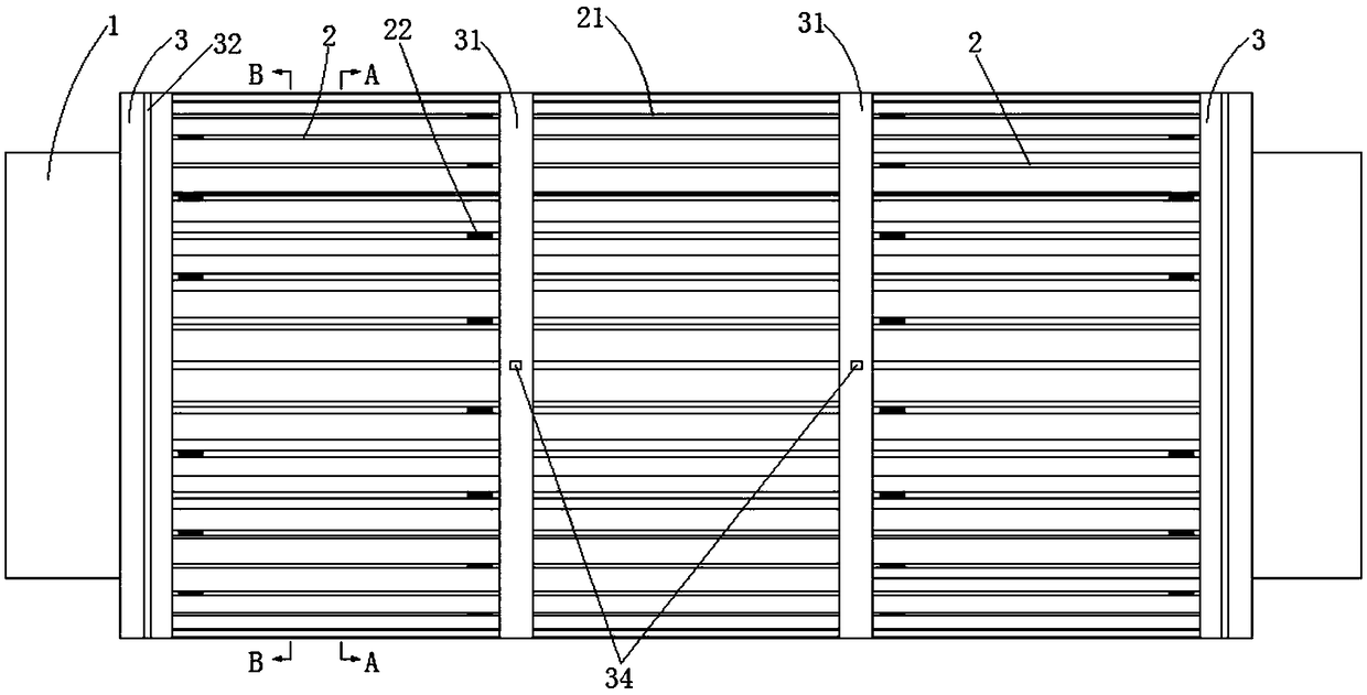
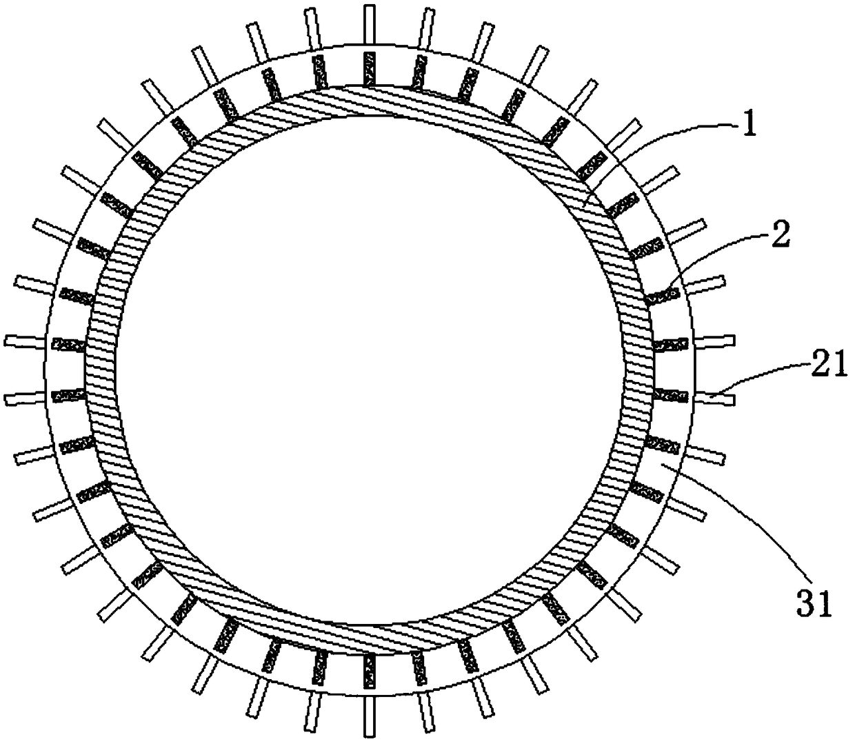
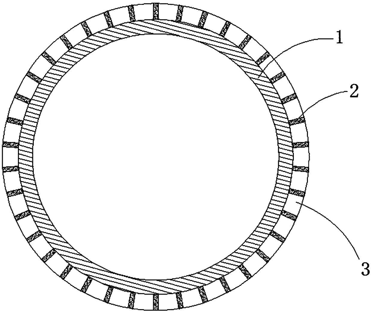
[0031] Such as Figure 1 to Figure 10 As shown, a motor base includes a base main body 1. In the present invention, extending along the center of the base main body 1 to the front and rear ends can be referred to as "outward". The direction of the end moving closer to the center can be called "inward", which is the "inner end" and "outer end" described in the following expressions.

[0032] The outer wall of the base body 1 is evenly distributed in the circumferential direction with the first cooling fins 21 and the second cooling fins 2, the first cooling fins 21 are located in the middle of the outer wall of the base main body 1, and the front and rear ends of the first cooling fins 21 are provided with There is a second heat sink 2, and an inner mounting ring 31 is attached between the first heat sink 21 and the second heat sink 2. The outer diam...


PUM


Abstract

The invention discloses a motor base. The motor base comprises a base body; first heat dissipation sheets and second heat dissipation sheets are uniformly distributed in the circumferential directionof the outer wall of the base body; the first heat dissipation sheets are positioned in the middle of the outer wall of the base body; both front and rear sides of the first heat dissipation sheets are each provided with the second heat dissipation sheets; the outer ends of the second heat dissipation sheets are coated through an upper cover plate and a lower cover plate; the upper cover plate andthe lower cover plate are semicircular structures; an upper sealing gasket abutting the outer end face of the second heat dissipation sheets is arranged on the inner wall of the upper cover plate ina fitting manner; a lower sealing gasket abutting the outer end face of the second heat dissipation sheets is arranged on the inner wall of the lower cover plate in a fitting manner; the outer end faces of the upper cover plate and the lower cover plate are spirally screwed into the top of the outer wall at the outer end of the base body, and tightly compressed; a second heat dissipation sheet positioned in the centre of the top is closed; other second heat dissipation sheets are each provided with a medium flow through hole; a medium inlet pipe and a medium outlet pipe are arranged on the topof the upper cover plate; and the medium inlet pipe and the medium outlet pipe are separately positioned at two sides of the second closed heat dissipation sheet. The motor base disclosed by the invention is good in cooling effect and convenient to clean.

Description

technical field [0001] The invention relates to the field of motors, in particular to a motor base. Background technique [0002] In order to improve the cooling effect, the existing motor base adopts water cooling or oil cooling. Its structure is to form a space for storing liquid cooling medium by casting or welding on the outer wall of the motor base, and the inside of the space is separated by a spacer. A plurality of small spaces are formed, and the liquid cooling medium is cooled sequentially through the small spaces. The structure of this type of motor base is such as an oil-cooled motor base with Chinese Patent No. 201720793282.4, and a water-cooled motor with Chinese Patent No. 201420203979.8. The cooling system structure of the frame, this type of motor frame has the following problems: [0003] 1. After long-term use, a large amount of dirt and impurities will accumulate in the space where the liquid cooling medium is stored, and the space is formed by casting or...

Claims


Application Information

Patent Timeline
Patent Type & Authority Applications(China)
IPC IPC(8): H02K5/18H02K5/20H02K9/19
CPCH02K5/18H02K5/20H02K9/19H02K2213/03
Inventor 葛素琴
Owner 葛素琴
Why Eureka
Eureka Blog
Learn More