
Electromagnetic excitation energy converter, laser projection optical sound screen, and synchronous display method thereof

An energy converter and electromagnetic excitation technology, which is applied in optics, instruments, sensors, etc., can solve the problems of separation of display screen and sound, inconvenient use, and large volume, so as to meet the needs of audio-visual experience and ensure the effect of not being disturbed

Active Publication Date: 2018-08-28
SICHUAN CHANGHONG ELECTRIC CO LTD
View PDF6 Cites 35 Cited by
  • Summary
  • Abstract
  • Description
  • Claims
  • Application Information

AI Technical Summary

Problems solved by technology

This solution enables the screen to vibrate to stimulate sound while controlling its vibration amplitude so that the human eye cannot detect it, ensuring that the display screen will not be disturbed, and forming a laser projection optical audio screen system solution that can not only display high-quality images but also play pleasant sounds. The traditional box-type audio set has many problems such as large volume, inconvenient use, separation of display screen and sound, etc., to meet the needs of users for audio-visual experience

Method used


Image

  • Electromagnetic excitation energy converter, laser projection optical sound screen, and synchronous display method thereof
  • Electromagnetic excitation energy converter, laser projection optical sound screen, and synchronous display method thereof
  • Electromagnetic excitation energy converter, laser projection optical sound screen, and synchronous display method thereof

Examples


Embodiment 1

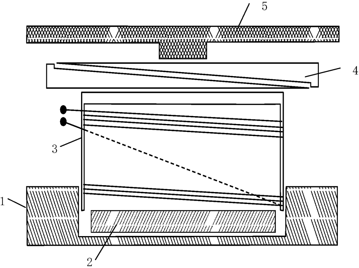
[0034] Such as figure 1 As shown, the electromagnetic excitation energy converter is composed of a metal shell 1, a strong magnetic ring / sheet 2, an excitation coil 3, an elastic reed 4, and a push arm bracket 5, wherein the strong magnetic ring / sheet 2 is closely attached to the metal Inside the shell 1, the excitation coil 3, the elastic reed 4 and the push arm bracket 5 are combined by glue, riveting, screws, etc., and then connected and fixed with the metal shell 1 through the elastic reed 4.

[0035] Specifically, the electromagnetic excitation energy converter is a device that specifically converts electrical energy into mechanical energy. The converter is used to push the screen or the auxiliary sounding board to vibrate, and each micro-element of the screen or the auxiliary sounding board radiates microcosmic disorder. Random uncorrelated signals of the same frequency but varying amplitude and phase that form the acoustic output. Its structure is composed of a metal s...

Embodiment 2

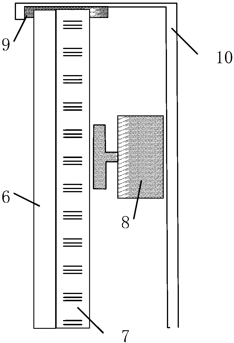
[0044] Such as figure 2 As shown, the hard laser projection optical sound screen is composed of a laser display screen 6, a hard rigid backboard 7, an electromagnetic excitation energy converter 8, an elastic suspension system 9 and a screen suspension bracket 10, wherein the laser display screen 6 and the hard The rigid backplane 7 is closely combined, and one end of the electromagnetic excitation energy converter 8 is connected to the rigid rigid backplane 7 , and the other end is connected to the screen suspension bracket 10 .

[0045] Specifically, the hard laser projection optical audio screen that uses the electromagnetic excitation energy converter to produce sound, the electromagnetic excitation energy converter is firmly combined with the rigid rigid backplane, and after the electric signal is input, the electromagnetic excitation energy converter pushes the hard rigid backplane , Driven to produce physical displacement and deformation, forming sound output.

[0046...

Embodiment 3

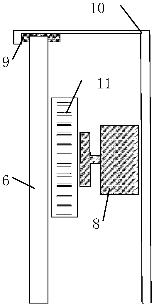
[0052] As shown in Figure 3, the flexible laser projection optical sound screen is composed of a laser display screen 6, an electromagnetic excitation energy converter 8, an elastic suspension system 9, a screen suspension bracket 10, and an auxiliary sound board 11, wherein the electromagnetic excitation energy converter 8 and After the auxiliary pronunciation board 11 is combined into a whole, one end of the whole is connected with the laser display screen 6 , and the other end is connected with the screen suspension bracket 10 . Specifically, as shown in Figure 3(a), the push arm support end of the electromagnetic excitation energy converter is closely bonded to the auxiliary sounding board, the auxiliary sounding board is bonded to the back of the laser display screen, and the electromagnetic excitation energy converter The end of the metal shell is closely bonded to the screen suspension bracket, or, as shown in Figure 3 (b), the push arm support end of the electromagnetic...


PUM


Abstract

The invention discloses an electromagnetic excitation energy converter, a laser projection optical sound screen, and a synchronous display method thereof, and relates to the technical field of the image display and the acoustics. A hard or flexible laser projection optical screen is used as display and sound production of a sound production component, the electromagnetic excitation energy converter is used for pushing the screen or an auxiliary sound production board to vibrate the same, thereby forming an acoustic output; a low pitch enhancing unit, a middle pitch enhancing unit and high pitch enhancing unit are further provided, and the graceful tone quality capable of covering the full frequency bands can be played through the processing of a power amplifier and a frequency divider; andthe sound-picture synchronization technology can be achieved through a specific algorithm and software processing. Through the scheme disclosed by the invention, the vibration amplitude of the screencan be controlled to be imperceptible by the human eye while the screen is vibrated to excite the sound production, thereby guaranteeing that the display picture cannot be interfered, and a laser projection optical sound screen system scheme capable of displaying excellent picture and playing the beautiful sound is formed, the problem that the traditional box type sound group is large in volume,inconvenient for use, and separated in picture display and sound is solved, and the audio visual experience demand of the user is satisfied.

Description

technical field [0001] Embodiments of the present invention relate to the fields of imaging display technology and acoustic technology, and more specifically, embodiments of the present invention relate to electromagnetic excitation energy converters, laser projection optical-acoustic screens and synchronous display methods thereof. Background technique [0002] Traditional display devices can only display images but cannot emit sound, so speakers are one of the most basic and important components of modern audio-visual systems, and their quality and shape directly affect the user experience of audio-visual systems. Modern flat panel display devices pursue thinner shapes, larger sizes, and more realistic sound fields. This popular trend makes traditional speakers nowhere to go. At present, the solutions for audio-visual systems are mostly ultra-thin flat speaker sets integrated with the display, or external SoundBar , or an external multi-channel speaker system, either the s...

Claims


Application Information

Patent Timeline
IPC IPC(8): H04R1/22H04R9/02H04R9/06G03B21/56
CPCG03B21/565H04R1/22H04R9/02H04R9/06
Inventor 陈宁石永庆周辉赵海龙岳定飞李志翔
Owner SICHUAN CHANGHONG ELECTRIC CO LTD
Learn More