TF card connector assembling machine

A card connector and assembly machine technology, applied in the field of assembly equipment, can solve the problems of high difficulty in manual assembly, poor quality of TF card connectors, slow assembly speed, etc., to save equipment space and processing equipment investment, save The effect of high production cost and labor cost input and high assembly efficiency

Active Publication Date: 2018-08-31
东莞市科晟电子有限公司
View PDF5 Cites 1 Cited by
  • Summary
  • Abstract
  • Description
  • Claims
  • Application Information

AI Technical Summary

Problems solved by technology

[0003] However, in the existing figure 2 The semi-finished product of the TF card connector shown in the figure is then assembled with the cam pin and the iron shell. The usual way is to assemble it by hand, but the manual assembly is difficult and the assembly speed is slow.
At the same time, the existing assembly machine is used to assemble the cam needle and the iron shell, and the assembly is carried out on a single device. In this way, multiple different devices are required to complete the assembly, thereby increasing the production cost. It is easy to cause the assembly of the assembled TF card connector to not be in place, and the quality of the TF card connector is not good.

Method used


Image

  • TF card connector assembling machine
  • TF card connector assembling machine
  • TF card connector assembling machine

Examples


Embodiment Construction

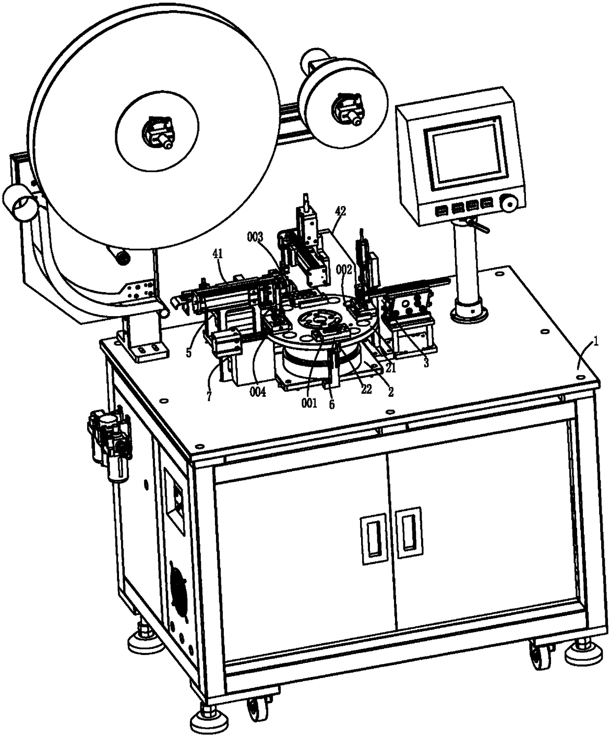
[0031] The present invention will be described in further detail below in conjunction with the accompanying drawings.

[0032] The embodiments described by referring to the figures are exemplary and are intended to explain the present application and should not be construed as limiting the present application. In the description of the present application, it should be understood that the terms "center", "longitudinal", "transverse", "length", "width", "thickness", "upper", "lower", "front", " Orientation or position indicated by "back", "left", "right", "vertical", "horizontal", "top", "bottom", "inner", "outer", "clockwise", "counterclockwise", etc. The relationship is based on the orientation or positional relationship shown in the drawings, and is only for the convenience of describing the present application and simplifying the description, rather than indicating or implying that the referred device or element must have a specific orientation, be constructed and operated ...


PUM


Abstract

The invention discloses a TF card connector assembling machine. The TF card connector assembling machine comprises a rotating disc component, a cam needle assembling component, an iron shell assembling component and a discharging component which are arranged on a machine case, wherein station fixtures used for the laying and loading of TF card connectors are circumferentially arrayed on the rotating disc component, and can be driven by the rotating disc component to intermittently rotate among a feeding station, a cam needle assembling station, an iron shell assembling station and a discharging station as well as to be butted with the cam needle assembling component, the iron shell assembling component and the discharging component; a cam needle can be fed by the cam needle assembling component to the matched station fixture and assembled with a semi-finished product of the corresponding TF card connector; the iron shell assembling component comprises a conveying device and a blanking-feeding device; the conveying device is used for conveying a conjoined iron shell coil material to a blanking station; the blanking-feeding device is used for manufacturing a single iron shell throughblanking, conveying the single iron shell to the matched station fixture, and assembling the single iron shell with the semi-finished product of the corresponding TF card connector into a finished product of the corresponding TF card connector; and the discharging assembly is used for sucking and discharging the finished product of the corresponding TF card connector on the matched station fixture to a receiving box.

Description

technical field [0001] The invention relates to the technical field of assembly equipment, in particular to a TF card connector assembly machine. Background technique [0002] At present, in the field of electronic equipment, TF card connectors are common access ports for external storage devices, and are widely used in the field of electronic equipment. Reference attached figure 1 The TF card connector, in the actual processing and composition process, is often completed by assembling the parts that make up the TF card connector in sequence. In practice, the composition is done in the attached figure 2 After the semi-finished product of the TF card connector shown, it is necessary to assemble the cam pin and the iron shell. [0003] However, in the existing figure 2 The semi-finished product of the TF card connector shown in the figure is then assembled with the cam pin and the iron shell, which is often assembled by manual assembly, but manual assembly is difficult a...

Claims


Application Information

Patent Timeline
Patent Type & Authority Applications(China)
IPC IPC(8): B23P21/00
CPCB23P19/001B23P21/006
Inventor 周家炜
Owner 东莞市科晟电子有限公司
Why Eureka
Try Eureka