Flow-dividing transferring opening for utility tunnel drainage cabin

A technology of integrated pipe gallery and transfer interface, applied in the direction of sewage discharge, drainage structures, water conservancy projects, etc., can solve the problem of high drainage pressure at the end of the pipe gallery, achieve the effect of convenient maintenance and meet drainage needs

Pending Publication Date: 2018-08-31
SHANGHAI MUNICIPAL ENG DESIGN INST GRP
View PDF0 Cites 3 Cited by
  • Summary
  • Abstract
  • Description
  • Claims
  • Application Information

AI Technical Summary

Problems solved by technology

[0003] The purpose of the present invention is to provide a diversion transfer interface for the drainage compartment of the comprehensive pipe gallery, which can overcome the problem of excessive drainage pressure at the end of the pipe gallery caused by the terrain problem and the inability to drain water in the middle due to the drainage pipeline being incorporated into the comprehensive pipe gallery

Method used


Image

  • Flow-dividing transferring opening for utility tunnel drainage cabin
  • Flow-dividing transferring opening for utility tunnel drainage cabin
  • Flow-dividing transferring opening for utility tunnel drainage cabin

Examples


Embodiment Construction

[0027] The "a diversion transfer interface for the drainage tank of the integrated pipe gallery" proposed by the present invention will be further described in detail in conjunction with the accompanying drawings and specific embodiments. The gist and features of the present invention will become clearer from the following description and claims. It should be noted that all the drawings are in a very simplified form and use imprecise scales, and are only used to facilitate and clearly assist the purpose of illustrating the embodiments of the present invention.

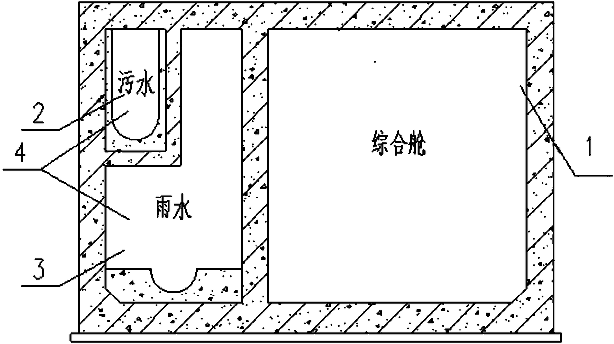
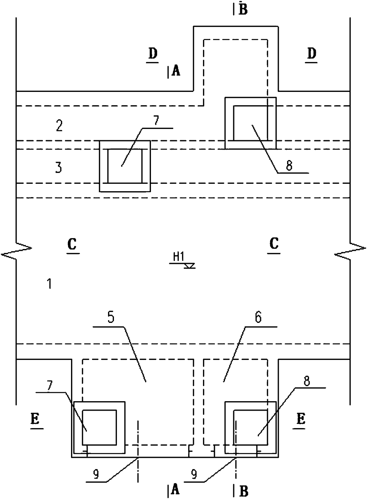
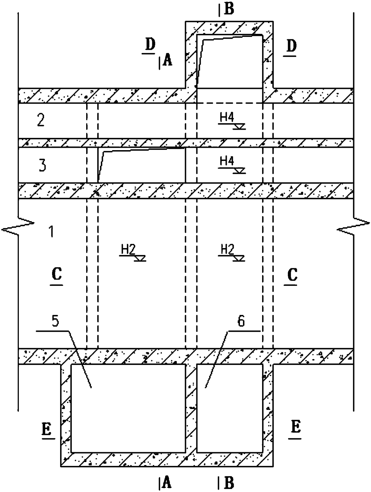
[0028] As shown in the figure, it is a diversion transfer interface of the drainage cabin of the comprehensive pipe gallery. The comprehensive pipe gallery includes the comprehensive cabin and the drainage cabin located on one side of the comprehensive cabin, and the drainage cabin includes the sewage tank culvert and the rainwater tank culvert. Its characteristics The diversion transfer interface includes a rainwater ...


PUM


Abstract

The invention discloses a flow-dividing transferring opening for a utility tunnel drainage cabin. The flow-dividing transferring opening comprises a rainwater and sewage passing tank culvert which isarranged on the lower portion of the standard section of a utility tunnel; the rainwater and sewage passing tank culvert comprises a rainwater passing tank culvert body communicating with a rainwatertank culvert cabin, and a sewage passing tank culvert body communicating with a sewage tank culvert cabin; drainage through-wall casing pipes are pre-embedded on wall plates at the ends of the rainwater passing tank culvert body and the sewage passing tank culvert body, and thus the rainwater passing tank culvert body and the sewage passing tank culvert body can be connected to a municipal drainage system in the direction perpendicular to the way side of the utility tunnel through a pipeline. According to the flow-dividing transferring opening for the utility tunnel drainage cabin, the problems that a traditional drainage piping enters the utility tunnel, the drainage lower points are located on the side close to an integrated cabin, rainwater and sewage cannot cross the tunnel integratedcabin to be drained in the process, consequently, the drainage pressure at the tail end is excessively large are solved; and by combining the arrangement of a corresponding rainwater inspection well and a sewage inspection well, the drainage requirements of land blocks on the two sides of a road are met, and meanwhile, overhauling is convenient.

Description

technical field [0001] The invention relates to the problem of drainage in the middle of a drainage pipeline entering a comprehensive pipe gallery, in particular to a diversion transfer interface of a drainage compartment of a comprehensive pipe gallery. Background technique [0002] In order to make intensive use of urban construction land and adapt measures to local conditions to benefit the longitudinal slope of roads, gravity flow pipelines such as rainwater and sewage and other municipal pipelines are included in the centralized management and arrangement of comprehensive utility corridors. For drainage pipelines entering corridors, some main lines and branch lines have long comprehensive pipe corridors, and all the rainwater and sewage collected in the plots along the lines are poured into the rainwater tanks of the pipe corridors, which will cause excessive drainage pressure at the end of the pipe corridors; because the comprehensive pipe corridors have certain Coveri...

Claims


Application Information

Patent Timeline
IPC IPC(8): E02D29/045E03F5/02E03F1/00
CPCE02D29/10E03F1/003E03F5/02
Inventor 高宇许大鹏郑国兴任永青郭启金仲良
Owner SHANGHAI MUNICIPAL ENG DESIGN INST GRP
Why Eureka
Try Eureka