
Screw rod transmission mechanism utilized in computer numerical control equipment

A technology of screw drive and numerical control equipment, applied in the direction of mechanical equipment, transmission devices, transmission device parts, etc., can solve the problems of large oil inlet and oil return pressure loss, easy to shake, etc., to reduce frictional resistance and improve transmission efficiency , the effect of reducing pressure loss

Pending Publication Date: 2018-08-31
平湖市祥瑞机械设备制造有限公司
View PDF0 Cites 1 Cited by
  • Summary
  • Abstract
  • Description
  • Claims
  • Application Information

AI Technical Summary

Problems solved by technology

[0003] With the advent of the era of industrialization, the old equipment used in the traditional machining industry is gradually replaced by CNC equipment. The screw drive mechanism is an indispensable part of the CNC equipment. However, the screw drive mechanism currently used in the CNC equipment It is easy to shake during the transmission process, and the pressure loss of the oil inlet and oil return of the screw drive mechanism after long-term use is relatively large

Method used


Image

  • Screw rod transmission mechanism utilized in computer numerical control equipment
  • Screw rod transmission mechanism utilized in computer numerical control equipment
  • Screw rod transmission mechanism utilized in computer numerical control equipment

Examples


Embodiment Construction

[0019] In order to make the technical means, creative features, goals and effects achieved by the present invention easy to understand, the present invention will be further described below in conjunction with specific embodiments.

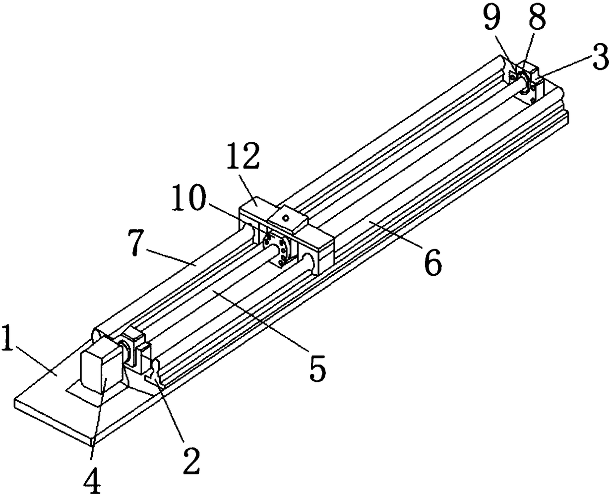
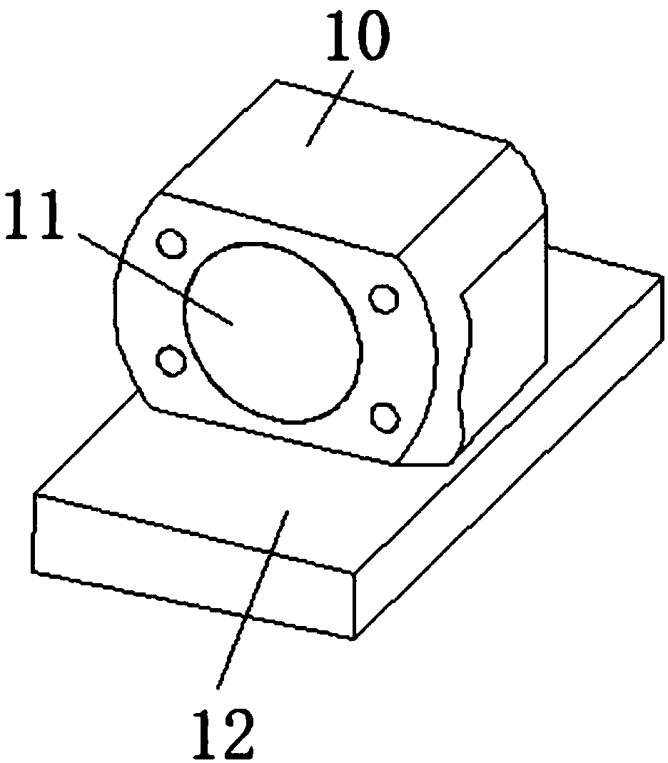
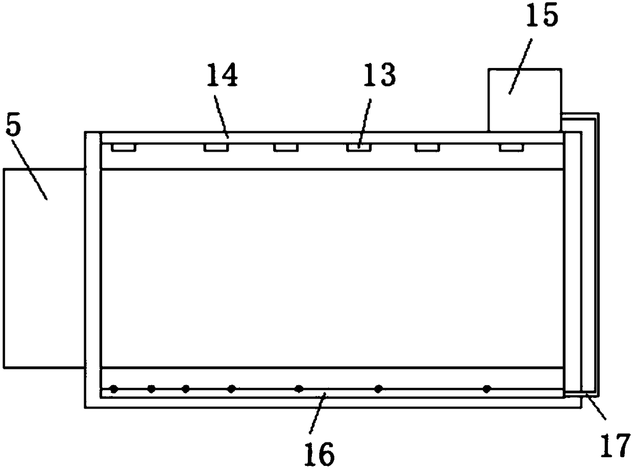
[0020] Such as Figure 1-3 As shown, a screw drive mechanism used in numerical control equipment includes a transmission seat 1, a No. 1 transmission plate 2 is arranged at one end above the transmission seat 1, and a No. 2 transmission plate 3 is provided at the other end above the transmission seat 1. One side of the No. 1 transmission plate 2 is equipped with a drive motor 4, one end of the drive motor 4 is movably connected to the screw mandrel 5, and the No. 1 drive plate 2 is connected to the No. 2 drive plate 3 by the screw mandrel 5, and the screw mandrel 5 One side is provided with a No. 1 auxiliary guide rod 6, and the other side of the screw mandrel 5 is provided with a No. 2 auxiliary guide rod 7. The No. 2 transmission plate 3 is conn...


PUM


Abstract

The invention discloses a screw rod transmission mechanism utilized in computer numerical control equipment. The screw rod transmission mechanism comprises a transmission seat, wherein a No.1 transmission plate is arranged at one end of the upper part of the transmission seat; a No.2 transmission plate is arranged at the other end of the upper part of the transmission seat; a driving motor is mounted on one side of the No.1 transmission plate; a screw rod is movably connected with one end of the driving motor; the No.1 transmission plate is connected with the No.2 transmission plate through the screw rod; a No.1 auxiliary guiding rod is arranged on one side of the screw rod; a No.2 auxiliary guiding rod is arranged on the other side of the screw rod; and the No.2 transmission plate is connected with the screw rod through a connecting shaft. The screw rod transmission mechanism disclosed by the invention has the beneficial effects that through the parallel arrangement of the screw rod as well as the No.1 auxiliary guiding rod and the No.2 auxiliary guiding rod which are positioned on two sides of the screw rod, the traction can be formed on the two sides of the screw rod during thetransmission process, and then the screw rod can be prevented from shaking up and down as well as left and right during the transmission process; during the work of computer numerical control precision equipment, the screw rod transmission mechanism can move smoothly and accurately; and the working efficiency and the working quality of a computer numerical control machine tool can be effectively improved.

Description

technical field [0001] The invention relates to the technical field of transmission mechanisms, in particular to a screw transmission mechanism used in numerical control equipment. Background technique [0002] The screw drive is an ideal product for converting rotary motion into linear motion, or converting linear motion into rotary motion. Lead screw is the most commonly used transmission element in tool machinery and precision machinery. Its main function is to convert rotary motion into linear motion, or convert torque into axial repeated force, and at the same time, it has high precision, reversibility and high efficiency. specialty. Due to its small frictional resistance, ball screws are widely used in various industrial equipment and precision instruments. [0003] With the advent of the era of industrialization, the old equipment used in the traditional machining industry is gradually replaced by CNC equipment. The screw drive mechanism is an indispensable part of ...

Claims


Application Information

Patent Timeline
IPC IPC(8): F16H25/20F16H25/24F16H57/04B23Q5/40
CPCF16H25/20F16H25/24F16H57/0456F16H57/0497B23Q5/40
Inventor 陆金波文涛
Owner 平湖市祥瑞机械设备制造有限公司
Learn More