
Novel water-saving faucet used for hot water

A faucet shell and faucet technology, applied in the field of faucets, can solve the problems of aggravated waste of water resources, unfavorable water conservation, waste of water resources, etc., and achieve the effect of low cost and reasonable control

Inactive Publication Date: 2018-08-31
CENXI DONGZHENG POWER TECH DEV
View PDF0 Cites 0 Cited by
  • Summary
  • Abstract
  • Description
  • Claims
  • Application Information

AI Technical Summary

Problems solved by technology

Existing faucets usually only include a water outlet and a control switch, and the user can change the water flow of the water outlet through a single control switch
When people use a water tap, they usually like to turn on the switch to the maximum to obtain the maximum water flow for washing or cleaning; To the maximum, use the largest water flow for washing, resulting in a waste of water resources; in today's society, water resources are relatively scarce, and the existing faucets are not conducive to saving water, which increases the unnecessary waste of water resources
[0003] At present, most of the water-saving faucets in the market have a relatively simple water outlet design, and the water output cannot be reasonably controlled. When the hot water needs to be released when it is connected to the water heater, it is caused by the need to let off a period of cold water before the hot water reaches the hot water outlet. The waste of water resources, long-term use of the accumulation of dirt inside the faucet will greatly harm the human body to drink

Method used


Image

  • Novel water-saving faucet used for hot water
  • Novel water-saving faucet used for hot water
  • Novel water-saving faucet used for hot water

Examples


Embodiment Construction

[0026] The following will clearly and completely describe the technical solutions in the embodiments of the present invention with reference to the accompanying drawings in the embodiments of the present invention. Obviously, the described embodiments are only some, not all, embodiments of the present invention. Based on the embodiments of the present invention, all other embodiments obtained by persons of ordinary skill in the art without making creative efforts belong to the protection scope of the present invention.

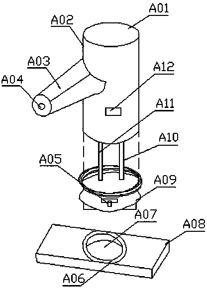
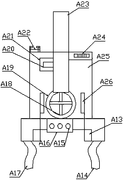
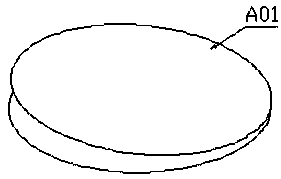
[0027] Embodiments of the present invention provide a novel water-saving faucet for hot water, such as Figure 1-4As shown, including the faucet housing (A02), the upper end of the faucet housing (A02) is provided with a pressing handle (A01), the surface of the faucet housing (A02) is provided with a nozzle head (A03), and the inside of the nozzle head (A03) is provided with a water outlet Spray hole (A04), the water-saving faucet has changed from a single wa...


PUM


Abstract

The invention provides a novel water-saving faucet used for hot water, and relates to the technical field of faucets. The novel water-saving faucet comprises a faucet shell, a pressing handle is arranged at the upper end of the faucet shell, a water outlet spraying hole is formed inside a spraying nozzle, a valve element is arranged inside the faucet shell, a threaded connecting pipe is arranged at the lower end of a water discharging channel, a microswitch is arranged at the upper end of the controller, a transmission wheel is arranged at the lower end of a control box, a transmission shaft is arranged inside the transmission wheel, sterilization channels are arranged on the two sides of the transmission wheel, sterilization modules are arranged at the lower ends of the sterilization channels, hot water pipes are arranged at the lower ends of the sterilization modules, and circulation pipes are arranged on one sides of the hot water pipes. The novel water-saving faucet solves the problems that at present, a water-saving faucet on the market is single in design, the water quantity cannot be controlled, water resources are wasted due to the fact that some cold water needs to be discharged away before the hot water enters a hot water outlet, and great harms are caused on drinking by people due to internal dirt accumulation inside the faucet after long-time use.

Description

technical field [0001] The invention relates to the technical field of faucets, in particular to a novel water-saving faucet for hot water. Background technique [0002] The faucet first appeared in the 16th century. It was cast in bronze. Its main function was to control the water outlet switch and the water flow of the water pipe. The early faucet was a spiral lift type. Most of the faucets on the market are ceramic valve core faucets. The lifting type has basically been eliminated. The replacement speed of the faucet is very fast, from the old-fashioned cast iron process to the electroplating knob type, and then to the stainless steel single temperature single control faucet, the stainless steel dual temperature dual control faucet, and the kitchen semi-automatic faucet. Now, more and more consumers are choosing faucets, and they will comprehensively consider materials, functions, shapes and other aspects. As a kind of water valve, the faucet is often used as a switch t...

Claims


Application Information

Patent Timeline
Patent Type & Authority Applications(China)
IPC IPC(8): F16K11/00F16K31/44F16K27/00F16K51/00E03C1/08
CPCE03C1/08F16K11/00F16K27/00F16K31/44F16K51/00
Inventor 关松生
Owner CENXI DONGZHENG POWER TECH DEV
Learn More