
Installation error identification method based on rotating shaft integration error measurement value

A technology of comprehensive error and installation error, which is applied in the field of identification of installation error of the rotating shaft based on the comprehensive error measurement value of the rotating shaft, can solve the problems that the rotating shaft is not perfect and the machining accuracy is easily affected by various errors, etc., and achieves strong applicability , The effect of simple measurement method

Inactive Publication Date: 2018-08-31
SOUTHWEST JIAOTONG UNIV +1
View PDF5 Cites 15 Cited by
  • Summary
  • Abstract
  • Description
  • Claims
  • Application Information

AI Technical Summary

Problems solved by technology

[0002] Compared with three-axis CNC machine tools, the machining accuracy of five-axis CNC machine tools is more susceptible to various errors (geometric errors, thermal errors, servo control errors, etc.); % or so (Sheng Bohao, Tang Hua. Comprehensive dynamic compensation technology for CNC machine tool errors [J]. Manufacturing Technology and Machine Tools, 1997(6):19-21.); At present, research on the measurement and identification of geometric errors of translation axes of five-axis CNC machine tools Relatively mature, but the geometric error measurement and identification of the rotating axis is not yet perfect

Method used


Image

  • Installation error identification method based on rotating shaft integration error measurement value
  • Installation error identification method based on rotating shaft integration error measurement value
  • Installation error identification method based on rotating shaft integration error measurement value

Examples


specific Embodiment

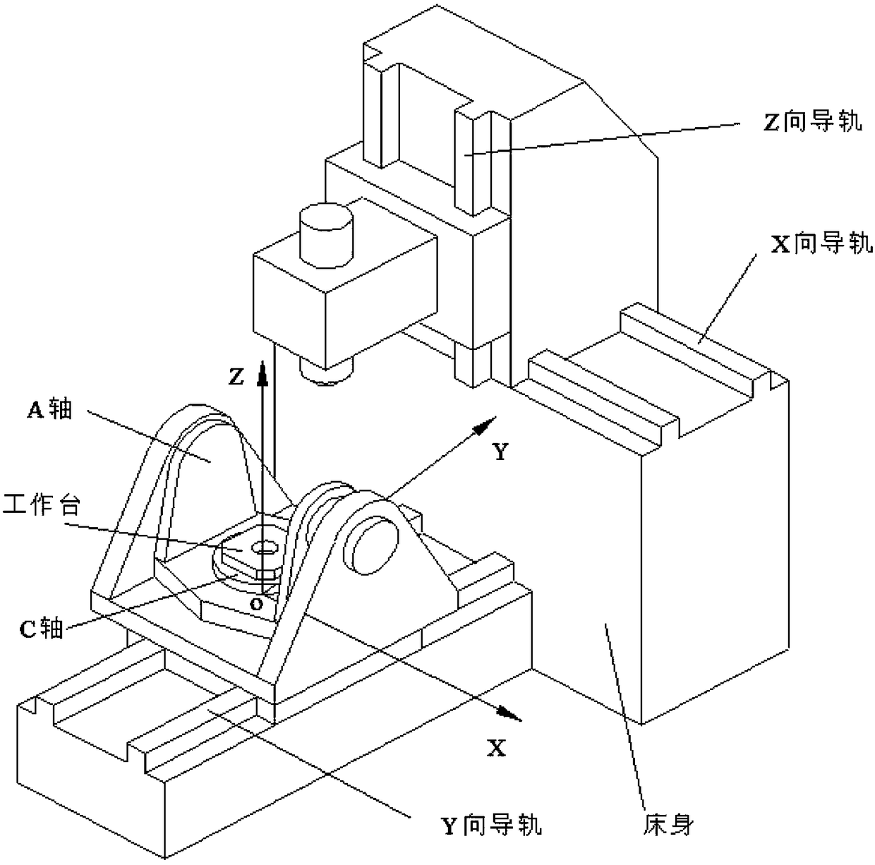
[0131] The C-axis of the HS664RT five-axis machining center of FIDIA Company is used to identify the installation error, and the measuring equipment is the R-test measuring instrument of IBS Company; the specific implementation steps and related measurement data and test results are as follows:

[0132] (1) The installation and commissioning of the R-test measuring instrument and the establishment of a measuring coordinate system, the measuring point corresponding to the measuring instrument P(x 0 ,y 0 ,z 0 ) in the measuring coordinate system is (0, 254, 100), the unit is mm;

[0133] (2) Prepare the measurement program, the test range is C-axis 0°~360°, every time the C-axis rotates 30°, pause for 3 seconds to perform a comprehensive error measurement of the measurement point, and measure once clockwise and counterclockwise;

[0134] (3) When measuring, turn on the RTCP function of the machine tool, and the comprehensive error measurement results are shown in Table 1;

[...


PUM


Abstract

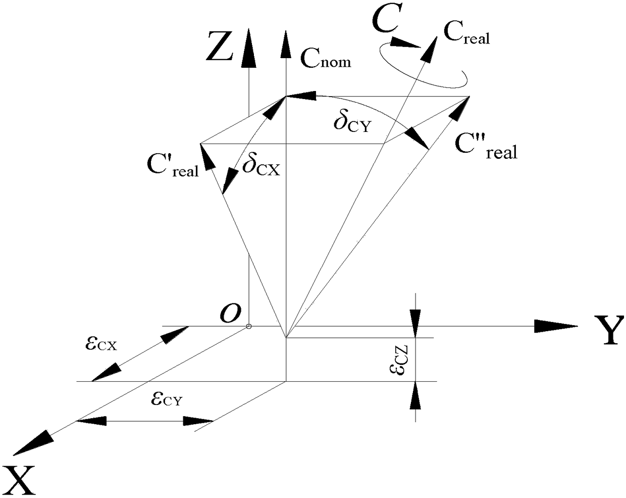
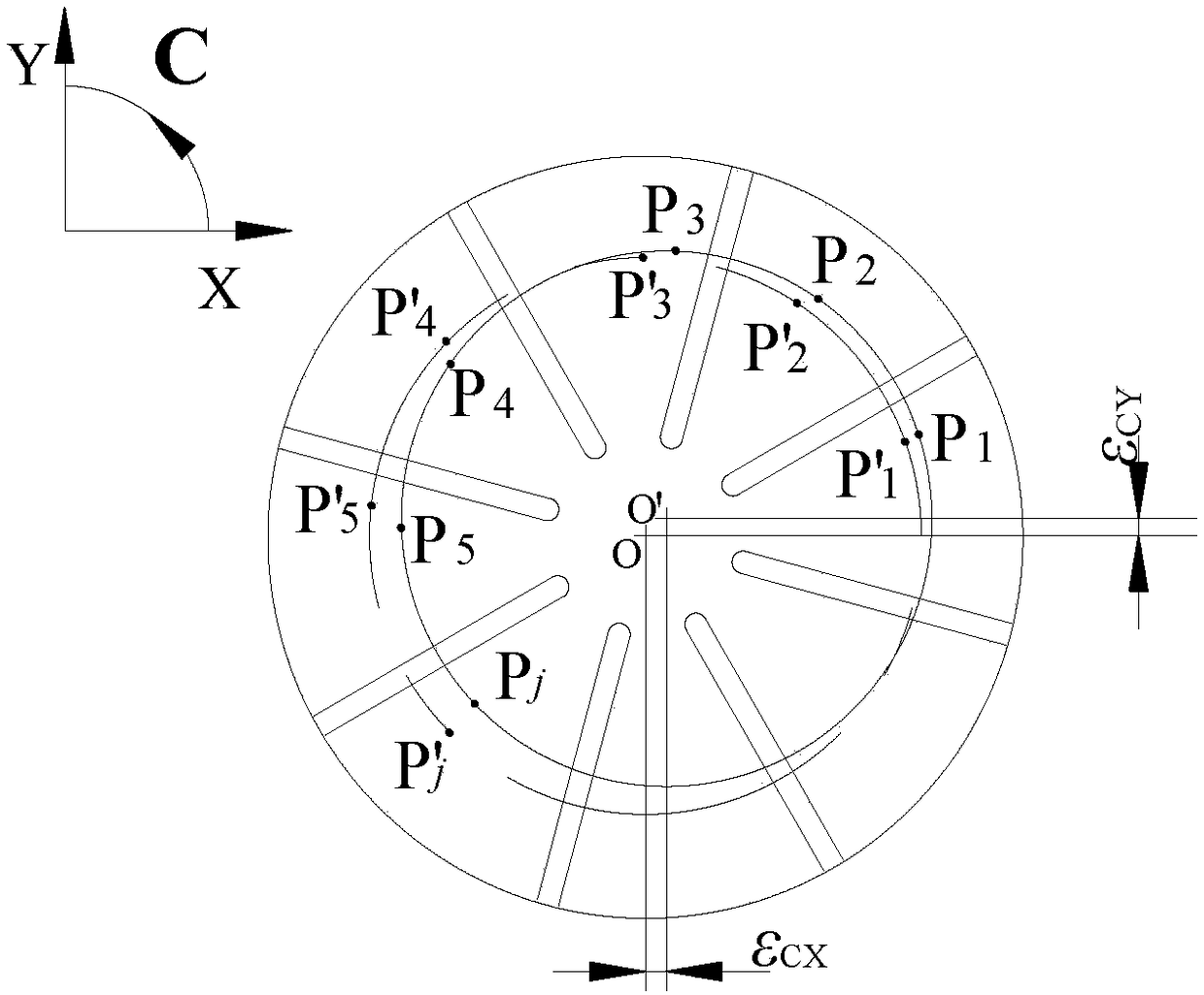
The invention discloses an installation error identification method based on a rotating shaft integration error measurement value. The method comprises the following steps of step1, taking the intersection point of a workbench rotation C rotation shaft axis and a workbench surface as an original point, and establishing a measured coordinate system; step2, through a measuring instrument, acquiringthe comprehensive error measurement value of the theoretical point and the actual point of the different rotation angles of a point P around a C shaft; step3, extracting the error projection point ofthe comprehensive error measurement value in an XOY measurement coordinate plane, and carrying out plane circle fitting to obtain the displacement error of a C shaft axis; and step4, extracting the error projection points of the comprehensive error measurement value in an XOZ measurement coordinate plane and a YOZ measurement coordinate plane, and carrying out straight line fitting and acquiring the perpendicularity errors of the C shaft, an X shaft and a Y shaft. In the invention, the four installation errors of the rotation shaft of a five-shaft numerical control machine tool can be conveniently, rapidly and accurately acquired, a data reference is provided for the assembling and debugging and the installation error of the rotation shaft of the five-shaft numerical control machine tool,and the method is suitable for all structural types of the five-shaft numerical control machine tools.

Description

technical field [0001] The invention belongs to the technical field of numerical control machining, and in particular relates to a method for identifying an installation error of a rotating shaft based on a comprehensive error measurement value of the rotating shaft. Background technique [0002] Compared with three-axis CNC machine tools, the machining accuracy of five-axis CNC machine tools is more susceptible to various errors (geometric errors, thermal errors, servo control errors, etc.); % or so (Sheng Bohao, Tang Hua. Comprehensive dynamic compensation technology for CNC machine tool errors [J]. Manufacturing Technology and Machine Tools, 1997(6):19-21.); At present, research on the measurement and identification of geometric errors of translation axes of five-axis CNC machine tools It is relatively mature, but the geometric error measurement and identification of the rotating shaft is not yet perfect. [0003] The geometric error of the rotary axis includes six motio...

Claims


Application Information

Patent Timeline
Patent Type & Authority Applications(China)
IPC IPC(8): G05B19/404
CPCG05B19/404G05B2219/33297G05B2219/37581
Inventor 江磊丁国富张历记丁国华张剑邹益胜
Owner SOUTHWEST JIAOTONG UNIV
Learn More