

Signal lamp fault detecting method, device, equipment and medium
A technology of fault detection and signal lights, which is applied in the field of traffic lights, can solve the problems of lagging repair work, poor real-time fault discovery, lagging repair information, etc.
- Summary
- Abstract
- Description
- Claims
- Application Information
AI Technical Summary
Problems solved by technology
Method used
Image

Examples
Embodiment 1
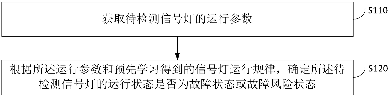
[0032] Figure 1a It is a flow chart of a signal lamp failure detection method provided by Embodiment 1 of the present invention. This embodiment is applicable to the situation of performing fault detection on signal lamps. The method can be executed by a signal lamp fault detection device, and the device can be realized by software and / or hardware. see Figure 1a , a signal lamp failure detection method provided in this embodiment includes:
[0033] S110. Obtain operating parameters of the signal lamp to be detected.
[0034] Wherein, the signal light to be detected is a traffic signal light at an intersection. The operating parameters are parameters during the operation of the signal lamp.
[0035] Typically, the operating parameters include: at least one of the change value of the parameter detection device and the maximum value, minimum value, difference value and average value of the parameter, wherein the parameters include current, voltage, active power, reactive pow...
Embodiment 2
[0050] figure 2 It is a flow chart of a signal lamp failure detection method provided by Embodiment 2 of the present invention. This embodiment proposes a method for judging a partial fault state based on the foregoing embodiments, taking the fault state as an example of a partial fault state as an example. see figure 2 , the signal detection method provided in this embodiment includes:
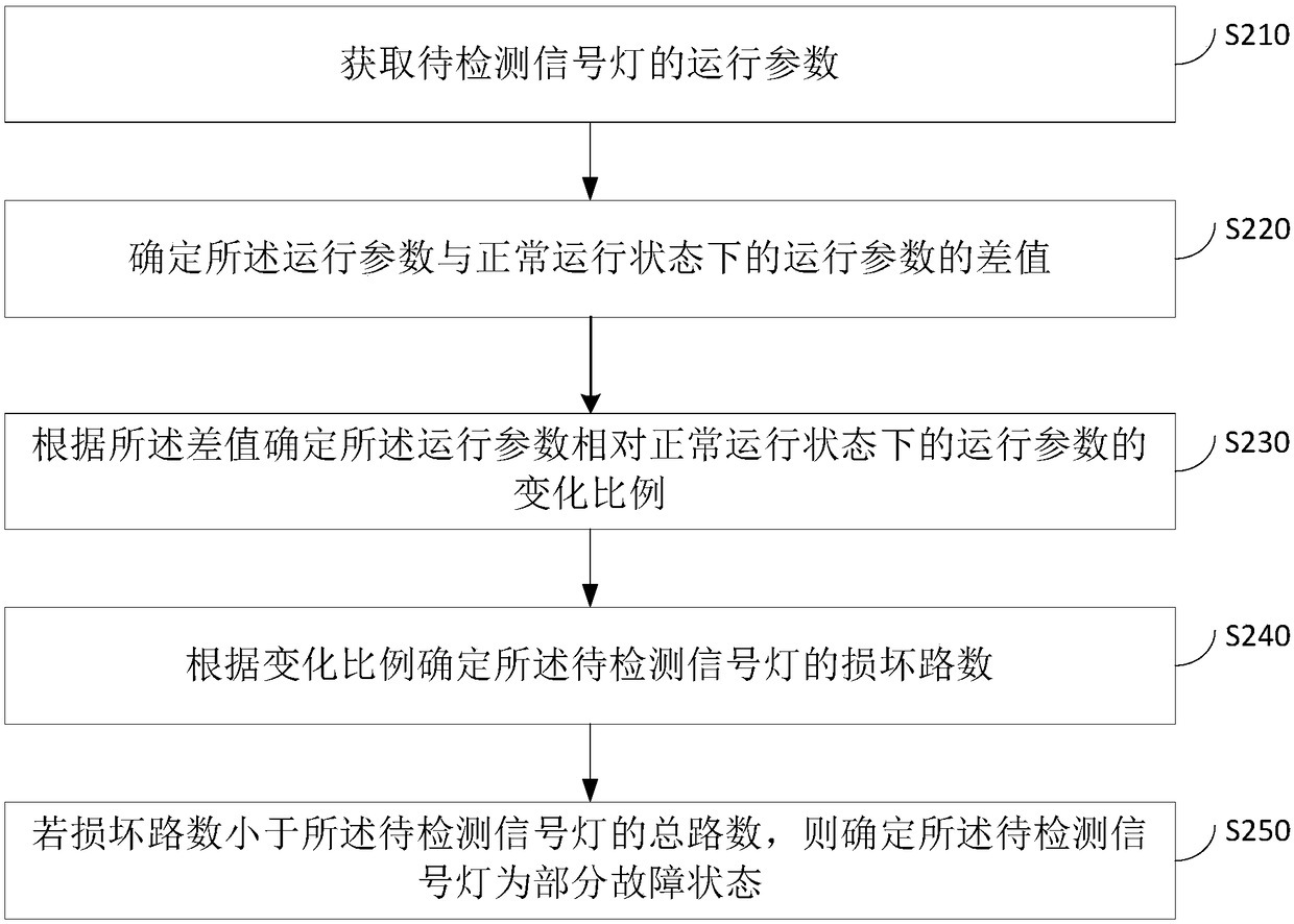
[0051] S210. Obtain operating parameters of the signal lamp to be detected.
[0052] S220. Determine the difference between the operating parameter and the operating parameter in a normal operating state.
[0053] S230. Determine, according to the difference, a change ratio of the operating parameter relative to an operating parameter in a normal operating state.
[0054] S240. Determine the number of damaged paths of the signal lamp to be detected according to the change ratio.
[0055]Usually, the signal light is composed of three street lights, which are red light, green light and y...
Embodiment 3
[0069] Figure 3a It is a flow chart of a signal lamp failure detection method provided by Embodiment 3 of the present invention. This embodiment is an optional solution proposed on the basis of the above embodiments in combination with factors of different working states of the signal lights. see Figure 3a , a signal lamp failure detection method provided in this embodiment includes:
[0070] S310. Obtain operating parameters of the signal lamp to be detected.
[0071] S320. Determine the working state of the signal lamp to be detected.
[0072] Wherein, the working state is always on and off state, blinking state or countdown state.
[0073] The manner of determining the working state of the signal lamp to be detected may be determined according to operating parameters, or may be determined according to the change law of the working state of the signal lamp and the current time.
[0074] S330. Determine the operating rule of the signal light according to the working st...
PUM
 Abstract
Description
Claims
Application Information