Automatic assembly machine for elastic piece type switches

An automatic assembly machine and shrapnel technology, applied in electrical switches, electrical components, circuits, etc., can solve the problems of inability to meet production development, easy to produce substandard products, low production efficiency, etc., and achieve ingenious structural design, high assembly efficiency, Easy-to-use effects

Inactive Publication Date: 2018-08-31
DONGGUAN UNIV OF TECH
View PDF0 Cites 18 Cited by
  • Summary
  • Abstract
  • Description
  • Claims
  • Application Information

AI Technical Summary

Problems solved by technology

[0002] The shrapnel switch includes a rubber shell 15, a shrapnel 17 and a button 16. When assembling, put the shrapnel 17 into the inside of the rubber shell 15, connect the two copper plugs at the lower end through the shrapnel 17, and buckle the button 16 with the rubber shell 15 for Toggle the shrapnel 17 to turn it on or off, but the assembly of the tact switch in the prior art is done by hand. The ordinary manpower assembly is generally divided into two stations. The first station is to assemble the body and the shrapnel. The shrapnel is sucked up with a suction pen and loaded into the body; the other station is the assembly button; then the assembled parts of the first station and the second station are sent to the press-in machine for final assembly, and the above-mentioned manual method assembles the shrapnel switch assembly The labor intensity is high, the production efficiency is low, and substandard products are likely to be produced, which affects the quality. Therefore, the manual assembly method is far from meeting the needs of production development.

Method used


Image

  • Automatic assembly machine for elastic piece type switches
  • Automatic assembly machine for elastic piece type switches
  • Automatic assembly machine for elastic piece type switches

Examples


Embodiment Construction

[0039] In order to enable those skilled in the art to better understand the technical solution of the present invention, the present invention will be described in detail below in conjunction with the accompanying drawings. The description in this part is only exemplary and explanatory, and should not have any limiting effect on the protection scope of the present invention. .

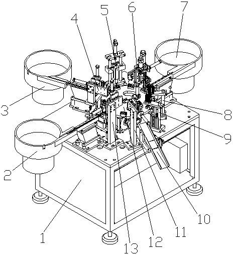
[0040] Such as Figure 1-Figure 14 As shown, the structure of the present invention is: an automatic assembly machine for shrapnel switches, which includes a frame 1, a power distribution control box, and a turntable 12 and a turntable drive device that are arranged on the frame 1 and cooperate with each other, and also include a uniformly arranged The fixture 14 on the upper edge of the turntable 12 is matched with the workpiece, and the surrounding of the turntable 12 is sequentially provided with a rubber shell feeding device 13 corresponding to the position of the fixture 14, a shrapnel feeding dev...


PUM


Abstract

The invention relates to switch assembly equipment, in particular to an automatic assembly machine for elastic piece type switches. The automatic assembly machine comprises a rack, a power distribution control box, a turntable, a turntable driving device and clamps, wherein the turntable and the turntable driving device are arranged on the rack and cooperated with each other, the clamps are uniformly arranged on the edge of the turntable and cooperate with workpieces; the periphery of the turntable is sequentially provided with a rubber shell feeding device, an elastic piece feeding device, aglue dispensing device and a button feeding device which correspond to the positions of the clamps in a rotating direction, and the devices above are all electrically connected with the power distribution control box and controlled by the power distribution control box. By arranging the turntable and sequentially arranging a rubber shell mounting station, an elastic piece mounting station, a gluedispensing station and a button mounting station on the turntable, integrated assembly of a rubber shell, an elastic piece and a button is completed on the turntable; by turning on and turning off a detection station, detection of a switched-on state and a switched-off state of the elastic piece switches is completed, and the efficiency of assembling the elastic piece switches is improved.

Description

technical field [0001] The invention relates to switch assembly equipment, in particular to an automatic assembly machine for shrapnel switches. Background technique [0002] The shrapnel switch includes a rubber shell 15, a shrapnel 17 and a button 16. When assembling, put the shrapnel 17 into the inside of the rubber shell 15, connect the two copper plugs at the lower end through the shrapnel 17, and buckle the button 16 with the rubber shell 15 for Toggle the shrapnel 17 to turn it on or off, but the assembly of the tact switch in the prior art is done by hand. The ordinary manpower assembly is generally divided into two stations. The first station is to assemble the body and the shrapnel. The shrapnel is sucked up with a suction pen and loaded into the body; the other station is the assembly button; then the assembled parts of the first station and the second station are sent to the press-in machine for final assembly, and the above-mentioned manual method assembles the ...

Claims


Application Information

Patent Timeline
Patent Type & Authority Applications(China)
IPC IPC(8): H01H11/00
CPCH01H11/00
Inventor 邓君龙建宇白云曾波
Owner DONGGUAN UNIV OF TECH
Why Eureka
Try Eureka