
Method for monitoring a machine tool, and controller

A technology of control department and machine tool, which is applied in computer control, general control system, program control, etc., can solve the problems of false alarms and weaken the sensitivity of monitoring methods, and achieve the effect of reducing the number of false alarms

Active Publication Date: 2018-08-31
高迈特德国有限公司
View PDF10 Cites 1 Cited by
  • Summary
  • Abstract
  • Description
  • Claims
  • Application Information

AI Technical Summary

Problems solved by technology

This in turn increases the risk of false alarms or reduces the sensitivity of the monitoring method

Method used


Image

  • Method for monitoring a machine tool, and controller
  • Method for monitoring a machine tool, and controller
  • Method for monitoring a machine tool, and controller

Examples


Embodiment Construction

[0040] Specific implementation plan

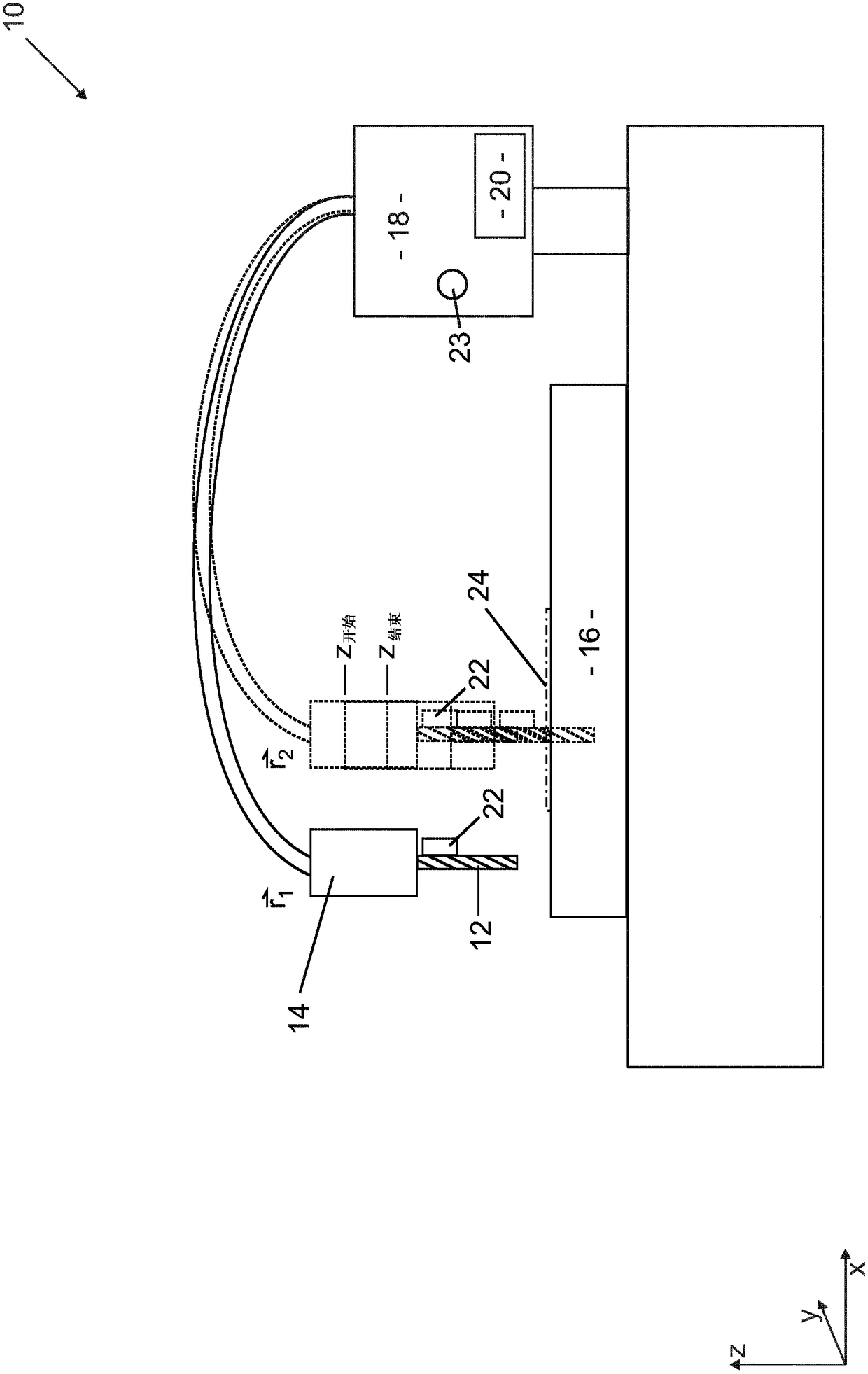
[0041] figure 1 A machine tool 10 with a tool 12 in the form of a drill is shown schematically. The tool 12 is driven by a spindle 14 schematically depicted. The workpiece 16 is clamped on the machine tool 10, and the workpiece is cut by the tool 12 within the scope of the machining process.

[0042] The spindle 14 and thus the tool 12 can be positioned in three spatial coordinates, namely along the x-direction, y-direction and z-direction. The corresponding drive is controlled by an electric control unit 18, which includes a digital memory 20. The computer numerical control program is stored in the digital memory 20. A program for executing the method according to the present invention is also stored in the digital memory 20 or a digital memory separated from it in space.

[0043] In addition, the machine tool may also have a sensor 22 schematically drawn, such as a force sensor or an acceleration sensor, which measures the acceleration of ...


PUM


Abstract

Provided is a method for monitoring a machine tool (10), in particular a material-removing machine tool (10), having the steps of: (a) determining process variable measured values (B(i)) of a processvariable (B) on the basis of a parameter, (b) determining whether the process variable measured values (B(i)) are in a predefined tolerance range (T(i)) which depends on the parameter, (c) if not, outputting a warning signal, and (d) constantly repeating steps (a) to (c), wherein the parameter is a control variable (i), in particular a scalar control variable, which always characterizes progress of the machining process. The invention provides for the control variable (i) to be calculated from the real time (t) and at least one process parameter (O, Atstiii) which characterizes the processingspeed of the machining process.

Description

Technical field [0001] The invention relates to a method for monitoring a machine tool, especially a cutting machine tool, according to the preamble of claim 1. [0002] According to a second aspect, the present invention relates to a control unit for a cutting machine tool, which has (a) a process parameter detection device that is set up to learn the process parameter measurement value of the process parameter depending on the parameter, And having (b) an arithmetic unit, which includes a digital memory. Background technique [0003] During cutting, such as milling, process parameters, such as the torque applied to the milling cutter, are constantly changing. If multiple components of the same type are manufactured and undergo processing multiple times, a characteristic trend of processing parameters with respect to time is obtained. If the machining process is disturbed, for example because the milling cutter breaks or because the workpiece is incorrectly clamped, the time cou...

Claims


Application Information

Patent Timeline
Patent Type & Authority Applications(China)
IPC IPC(8): G05B19/4062
CPCG05B19/4062G05B19/406G05B2219/31455
Inventor 扬-维尔姆·布林克豪斯约阿希姆·伊米埃拉
Owner 高迈特德国有限公司
Learn More