Target secondary discrimination method after constant false alarm rate detection

A technology of constant false alarm detection and target, applied in the field of radar, can solve the problems of false alarm, target detection performance impact, and it is difficult to refer to the unit to improve the detection threshold.

Pending Publication Date: 2021-04-20
XIDIAN UNIV
View PDF0 Cites 1 Cited by
  • Summary
  • Abstract
  • Description
  • Claims
  • Application Information

AI Technical Summary

Problems solved by technology

[0005] However, since the adaptive detection threshold is estimated by using the data units around the unit to be detected, the performance of target detection will inevitably be affected by the clutter suppression algorithm
Discrete clutter in the unit to be detected may cross the detection threshold, causing false alarms
In practice, isolated buildings such as power towers, wind turbine

Method used


Image

  • Target secondary discrimination method after constant false alarm rate detection
  • Target secondary discrimination method after constant false alarm rate detection
  • Target secondary discrimination method after constant false alarm rate detection

Examples


Embodiment 1

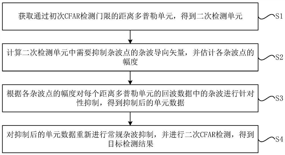
[0044] See figure 1 , figure 1 It is a flow chart of a target secondary screening method after constant false alarm detection provided by an embodiment of the present invention, including the following steps:

[0045] S1: Obtain the range Doppler unit that passes the primary CFAR detection threshold to obtain the secondary detection unit.

[0046] Specifically, the CFAR detector is firstly used to perform initial point-by-point detection on each unit in the range Doppler plane, and the position information {(I k ,J k ), k=1,2,...,K}, K secondary detection units are obtained. Among them, K is the number of range Doppler units that pass the CFAR detection threshold.

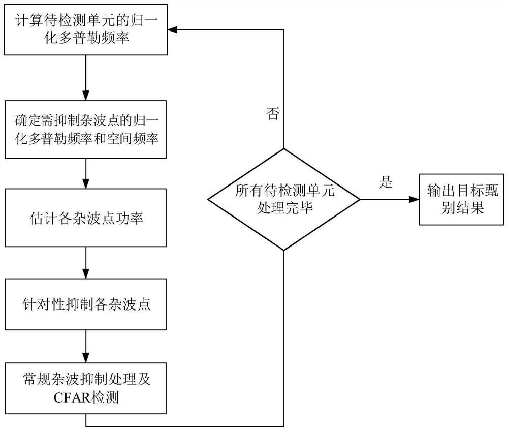
[0047] S2: Calculate the clutter steering vector of the clutter point that needs to be suppressed in the secondary detection unit, and estimate the amplitude of each clutter point, specifically including:

[0048] S21: Calculate the distance in the secondary detection unit and the normalized Doppler frequency ...

Embodiment 2

[0091] The beneficial effects of the secondary discrimination method after the constant false alarm detection provided by the above-mentioned embodiment 1 are further verified and explained through simulation experiments.

[0092] Experimental conditions:

[0093] Set the flight altitude of the carrier aircraft h a The array antenna adopts a 16×1 uniform linear array, and the array element spacing l is 0.1m. The speed direction of the aircraft is parallel to the array axis, that is, the front side-view array, and the angle between the main beam pointing and the array axis is 90°, and the elevation angle of the main beam is 0°. Carrier frequency f c 1.5GHz, wavelength λ 0 The distance sampling frequency used by the radar is 2MHz, the pulse repetition frequency is 3000Hz, and the pulse number is 64.

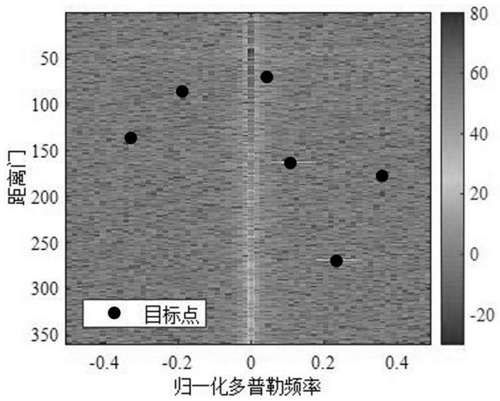
[0094] Experiment content:

[0095] In this simulation experiment, the target signal was added at the No. 137 range gate with a normalized Doppler frequency of -0.3281 and the...


PUM


Abstract

The invention discloses a target secondary discrimination method after constant false alarm detection, and the method comprises the steps: obtaining a distance Doppler unit passing through a primary CFAR detection threshold, and obtaining a secondary detection unit; calculating clutter steering vectors of clutter points needing to be suppressed in the secondary detection unit, and estimating the amplitude of each clutter point; according to the amplitude of each clutter point, suppressing clutters in the echo data of each distance Doppler unit in a targeted mode, and obtaining suppressed unit data; and performing conventional clutter suppression on the suppressed unit data again, and performing secondary CFAR detection to obtain a target detection result. According to the target secondary discrimination method after constant false alarm detection provided by the invention, the number of false alarms is reduced, and the burden of a subsequent radar data processor is reduced; and the method is small in calculation amount and easy to implement in engineering.

Description

technical field [0001] The invention belongs to the technical field of radar, and in particular relates to a method for secondary discrimination of targets after constant false alarm detection. Background technique [0002] Airborne radar detects and tracks moving targets of interest such as aircraft, ships, and missiles by emitting electromagnetic waves and receiving echoes. However, radar echoes not only contain possible target signals, but often also contain reflection signals from other objects in the radar scene, such as ground clutter reflected from the ground and meteorological clutter reflected from clouds and rain. Due to the movement of the platform, the clutter occupies a certain width at the Doppler frequency, and the power density of the clutter is modulated by the irradiation pattern, which also changes with the angle or the Doppler frequency. The energy of the main lobe of the radar beam is very strong, and the energy of the ground echo in the irradiation are...

Claims


Application Information

Patent Timeline
IPC IPC(8): G01S7/41
Inventor 王彤李仲悦
Owner XIDIAN UNIV
Why Eureka
Try Eureka