Thermoelectric module

A technology of thermoelectric modules and thermocouples, which is applied in the manufacture/processing of circuits, thermoelectric devices, electrical components, etc., can solve problems such as low output power, lower output voltage, lower output or performance characteristics, etc., and achieve high reliability.

Inactive Publication Date: 2018-08-31
EURON THERMODYNAMICS
View PDF15 Cites 0 Cited by
  • Summary
  • Abstract
  • Description
  • Claims
  • Application Information

AI Technical Summary

Problems solved by technology

[0007] However, known thermoelectric modules with improved fault tolerance often have significantly reduced output or performance characteristics compared to standard thermoelectric modules, even before failure
For example, known thermoelectric ge

Method used


Image

  • Thermoelectric module
  • Thermoelectric module
  • Thermoelectric module

Examples


Embodiment Construction

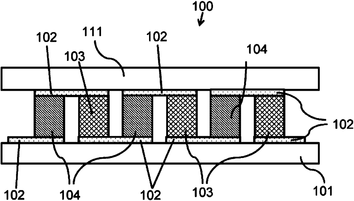
[0048] figure 1 is a side view of a standard thermoelectric module 100 known in the art. The thermoelectric module 100 includes a bottom substrate 101 , electrical interconnects 102 disposed on the bottom substrate 101 , n-type thermoelectric elements 104 , p-type thermoelectric elements 103 , and electrical interconnects 102 disposed on a top substrate 111 . Electrical interconnect 102 connects n-type 104 and p-type 103 thermoelectric elements in series, forming a series of electrically connected thermocouples.

[0049] The thermoelectric module 100 may be electrically connected to an external power source to provide electrical cooling or heating, or thermally connected between temperature differences to generate electricity.

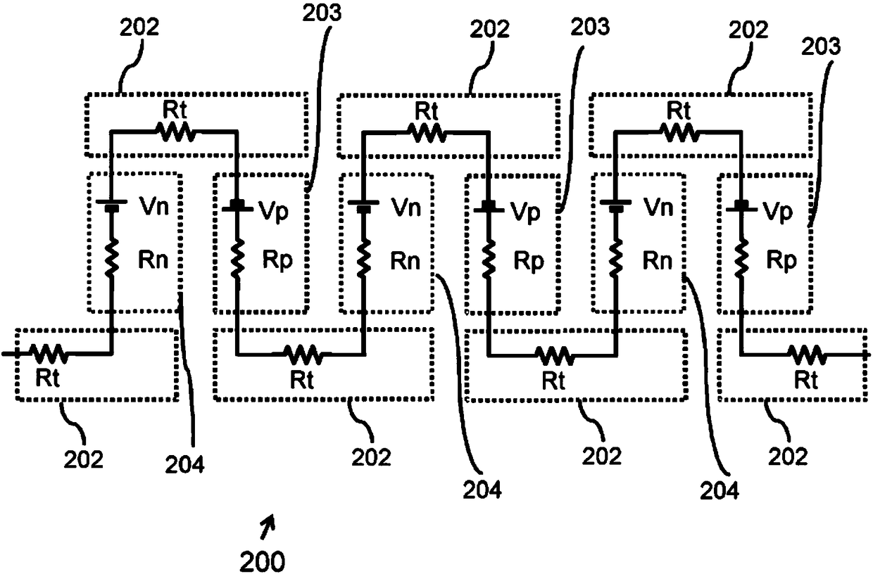
[0050] figure 2 shown in figure 1 Electrical schematic diagram of the thermoelectric module in . Thermoelectric elements 103 and 104, and the electrical interconnects 102 interfacing therewith, can be represented by equivalent circuits 203 and 204...


PUM


Abstract

A thermoelectric module comprising: a plurality of thermocouples electrically connected in series to provide a main electrical path through the thermoelectric module, each thermocouple comprising an n-type thermoelectric element and a p-type thermoelectric element; and at least one shunt electrical path connected in parallel to a portion of the main electrical path, the portion of the main electrical path comprising at least one of the n-type and/or p-type thermoelectric elements; wherein the resistance of a given shunt electrical path is less than the resistance of the main electrical path and more than the resistance of the portion of the main electrical path with which the given shunt electrical path is in parallel.

Description

technical field [0001] The invention relates to a thermoelectric module, more specifically, to a thermoelectric module with higher fault tolerance and output characteristics. Background technique [0002] Thermoelectric modules can be used in devices to cool, heat or generate electricity. Thermoelectric modules are all solid-state, with no moving parts, so they are typically lighter, smaller, and quieter than equivalent mechanical systems. Thermoelectric modules are often used in applications requiring high reliability and long service life. For example, a thermoelectric generator comprising one or more thermoelectric modules can be used to provide low-maintenance power supply to equipment located in remote or difficult-to-access locations. As such, thermoelectric devices are also environmentally friendly and relatively inexpensive, for example, by eliminating the need for frequent battery replacements. [0003] In general, standard thermoelectric modules are not tolerant...

Claims


Application Information

Patent Timeline
IPC IPC(8): H01L35/32
CPCH10N10/13H10N10/01H10N10/17H02H9/041H10N19/00
Inventor 理查德·涂勒凯文·辛普森
Owner EURON THERMODYNAMICS
Why Eureka
Try Eureka