A method for calculating signal-to-noise ratio and user equipment ue

A signal-to-noise ratio and computing unit technology, applied in the field of communication, can solve the problems of wasting storage resources and low computing speed, and achieve the effect of saving storage resources and improving computing speed.

Active Publication Date: 2021-07-09
HUAWEI TECH CO LTD
0 Cites 0 Cited by

AI-Extracted Technical Summary

Problems solved by technology

[0004] Since there will be interpolation coefficients in the specific method for calculating the third SNR above, and the interpolation coefficients are tightly coupled with the modulation order and coding efficiency, resulting in the prediction of BLER ...

Method used

[0138] Secondly, in order to reflect the correlation of the channel, this embodiment further optimizes the first correction coefficient, the second correction coefficient, the third correction coefficient, the ...

Abstract

The invention discloses a method for calculating the signal-to-noise ratio and a UE, which can save storage resources and improve the calculation rate. The method in the embodiment of the present invention includes: acquiring a pilot signal; calculating the channel coefficient value corresponding to the pilot signal; calculating each subcarrier of the target data stream according to the current signal-to-noise ratio, the channel coefficient value, and related parameters of the linear receiver The first SNR of the signal-to-noise ratio SNR, and calculate the second SNR of each subcarrier under the ideal interference cancellation; Calculate the first average received bit information rate RBIR of the subcarrier of the target data stream according to the first SNR, and according to The second SNR calculates the second average RBIR of the subcarrier of the target data stream; calculates the maximum likelihood receiver according to the first average RBIR, the second average RBIR, the first interpolation coefficient, and the second interpolation coefficient is a third average RBIR, the first interpolation coefficient is related to a modulation order, and the second interpolation coefficient is related to coding efficiency; mapping the third average RBIR to a third SNR.

Application Domain

Technology Topic

Image

  • A method for calculating signal-to-noise ratio and user equipment ue
  • A method for calculating signal-to-noise ratio and user equipment ue
  • A method for calculating signal-to-noise ratio and user equipment ue

Examples

  • Experimental program(1)

Example Embodiment

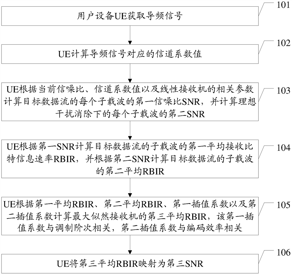
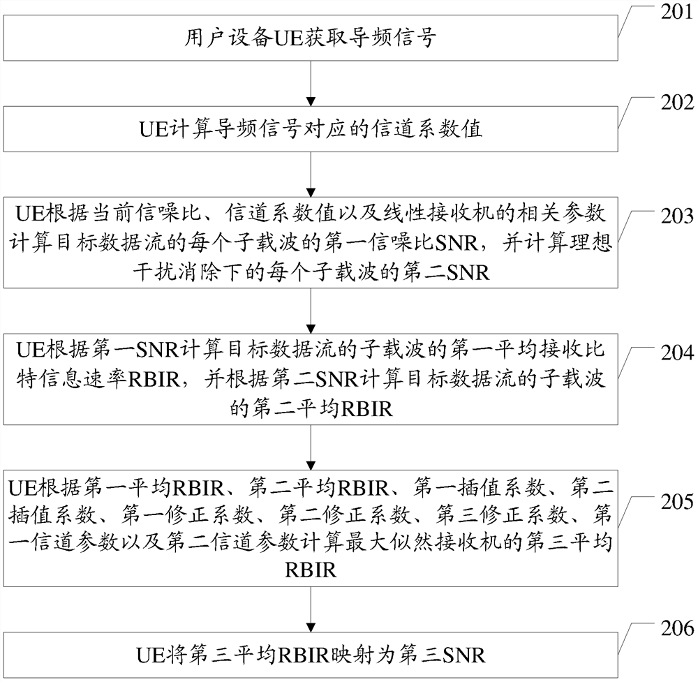
[0073] Embodiments of the present invention provide a method and UE for calculating a signal-to-noise ratio, which can save storage resources and improve calculation rate.
[0074] In order to make those skilled in the art better understand the solutions of the present invention, the technical solutions in the embodiments of the present invention will be clearly and completely described below with reference to the accompanying drawings in the embodiments of the present invention. Obviously, the described embodiments are only Embodiments are part of the present invention, but not all embodiments. Based on the embodiments of the present invention, all other embodiments obtained by persons of ordinary skill in the art without creative efforts shall fall within the protection scope of the present invention.
[0075] The terms "first", "second", "third", "fourth", etc. (if present) in the description and claims of the present invention and the above-mentioned drawings are used to distinguish similar objects and are not necessarily used to Describe a particular order or sequence. It is to be understood that data so used may be interchanged under appropriate circumstances so that the embodiments described herein can be practiced in sequences other than those illustrated or described herein. Furthermore, the terms "comprising" and "having" and any variations thereof, are intended to cover non-exclusive inclusion, for example, a process, method, system, product or device comprising a series of steps or units is not necessarily limited to those expressly listed Rather, those steps or units may include other steps or units not expressly listed or inherent to these processes, methods, products or devices.
[0076] see figure 1 , an embodiment of the method for calculating the signal-to-noise ratio in the embodiment of the present invention includes:
[0077] 101. User equipment UE acquires a pilot signal;
[0078] In this embodiment, in order to obtain the signal coefficient value, the UE obtains the pilot signal.
[0079] It should be noted that the pilot signal may be a kind of reference signal (full English name: Reference Signal, English abbreviation: RS).
[0080] 102. The UE calculates a channel coefficient value corresponding to the pilot signal;
[0081] After the UE acquires the pilot signal, the UE calculates the channel coefficient value corresponding to the pilot signal by using the pilot signal.
[0082] 103, UE calculates the first signal-to-noise ratio SNR of each subcarrier of the target data stream according to the current signal-to-noise ratio, channel coefficient value and the relevant parameters of the linear receiver, and calculates the second SNR of each subcarrier under ideal interference cancellation;
[0083] After the UE calculates and obtains the channel coefficient value, the UE obtains the current signal-to-noise ratio, and the UE calculates the first signal-to-noise ratio SNR of each subcarrier of the target data stream according to the current signal-to-noise ratio, the channel coefficient value and the related parameters of the linear receiver, and Calculate the second SNR for each subcarrier under ideal interference cancellation.
[0084] It should be noted that the linear receiver includes a linear minimum mean square error (full English name: Minimum mean square error, English abbreviation: MMSE) receiver.
[0085] 104, the UE calculates the first average received bit information rate RBIR of the subcarriers of the target data stream according to the first SNR, and calculates the second average RBIR of the subcarriers of the target data stream according to the second SNR;
[0086]After the UE calculates and obtains the first SNR and the second SNR, the UE calculates the first average received bit information rate RBIR of the subcarriers of the target data stream according to the first SNR, and calculates the second average received bit information rate RBIR of the subcarriers of the target data stream according to the second SNR Average RBIR.
[0087] It should be noted that the UE calculates the RBIR of each subcarrier, and after calculating the RBIR of all the subcarriers, the UE takes an average value to obtain the average RBIR of all the subcarriers of the target data stream.
[0088] Optionally, in some embodiments of the present invention, the UE calculates the first average received bit information rate RBIR of the subcarriers of the target data stream according to the first SNR, and calculates the second average received bit information rate RBIR of the subcarriers of the target data stream according to the second SNR. The average RBIR is specifically:
[0089] The first average RBIR and the second average RBIR are calculated by the following formulas:
[0090] as well as
[0091] where RBIR MMSE and RBIR IF represent the first average RBIR and the second average RBIR, respectively, N C is the number of subcarriers in the data stream, represents the first SNR, represents the second SNR. and Satisfy the following formula:
[0092] as well as
[0093] in, represents the RBIR of the Kth subcarrier of the target data stream corresponding to the first SNR, Indicates the RBIR of the Kth subcarrier of the target data stream corresponding to the second SNR, log 2 (m k MMSE ) represents the number of bits transmitted on the Kth subcarrier of the target data stream corresponding to the first SNR, log 2 (m IF k ) represents the number of bits transmitted on the Kth subcarrier of the target data stream corresponding to the second SNR, Indicates that the Kth subcarrier of the target data stream has a first SNR of Mutual information when the modulation order is m, Indicates that the Kth subcarrier of the target data stream has a second SNR of mutual information for modulation order m, and as well as Satisfy the following formula:
[0094]
[0095] in Probability density function representing the symbol-level log-likelihood ratio of the jth constellation point when the SNR is equal to γ.
[0096] 105. The UE calculates the third average RBIR of the maximum likelihood receiver according to the first average RBIR, the second average RBIR, the first interpolation coefficient, and the second interpolation coefficient, where the first interpolation coefficient is related to the modulation order, and the second interpolation coefficient is related to coding efficiency;
[0097] After the UE calculates and obtains the first average RBIR and the second average RBIR, the UE calculates the third average RBIR of the maximum likelihood receiver according to the first average RBIR, the second average RBIR, the first interpolation coefficient and the second interpolation coefficient. One interpolation coefficient is related to the modulation order, and the second interpolation coefficient is related to the coding efficiency.
[0098] Optionally, in some embodiments of the present invention, the UE calculates the third average RBIR of the maximum likelihood receiver according to the first average RBIR, the second average RBIR, the first interpolation coefficient and the second interpolation coefficient, specifically:
[0099] The third average RBIR is calculated by the following formula:
[0100] RBIR ML =β m (RBIR IF -RBIR MMSE )+RBIR MMSE +α γ;
[0101] Among them, RBIR MMSE , RBIR IF and RBIR ML are the first average RBIR, the second average RBIR, and the third average RBIR, respectively, and β m is the first interpolation coefficient, α γ is the second interpolation coefficient.
[0102] It should be noted that, in practical application, if there are M different modulation orders and N different coding efficiencies, the number of fitting parameters to be stored in the present invention is (M+N), and the first interpolation coefficient β m It is only related to the modulation order, and different modulation orders correspond to different β m value. Similarly, the second interpolation coefficient α γ It is only related to the coding efficiency, different coding efficiencies correspond to different α γ value.
[0103] 106. The UE maps the third average RBIR to the third SNR.
[0104] After the UE calculates and obtains the third average RBIR, the UE maps the third average RBIR to the third SNR.
[0105] Optionally, in some embodiments of the present invention, after the UE maps the third average RBIR to the third SNR, the method includes:
[0106] The UE determines the channel quality indicator CQI according to the third SNR;
[0107] The UE sends the CQI to the base station.
[0108] It should be noted that after receiving the CQI, the base station will recalculate the CQI, and send a signal to the UE according to the recalculated CQI.
[0109] In this embodiment, since the first interpolation coefficient of the present invention is related to the modulation order, and the second interpolation coefficient is related to the coding efficiency, which is different from the prior art, the interpolation coefficient has nothing to do with the modulation order and coding efficiency, so it reduces the need for Therefore, the present invention can save storage resources and improve the calculation rate.
[0110] Secondly, this embodiment introduces the method for calculating the second average RBIR and the method for calculating the third average RBIR in detail, so that the present invention is more specific.
[0111] Finally, the UE according to the present invention determines the CQI according to the third SNR, and sends the CQI to the base station, so that the base station can recalculate the CQI, and then sends a signal to the UE.
[0112] Since the existing solution does not optimize the channel correlation, the present invention further optimizes it in order to reflect the channel correlation. Please refer to figure 2 , another embodiment of the method for calculating the signal-to-noise ratio in the embodiment of the present invention includes:
[0113] 201. User equipment UE acquires a pilot signal;
[0114] 202. The UE calculates a channel coefficient value corresponding to the pilot signal;
[0115] 203, the UE calculates the first signal-to-noise ratio SNR of each subcarrier of the target data stream according to the current signal-to-noise ratio, the channel coefficient value and the related parameters of the linear receiver, and calculates the second SNR of each subcarrier under ideal interference cancellation;
[0116] 204, the UE calculates the first average received bit information rate RBIR of the subcarriers of the target data stream according to the first SNR, and calculates the second average RBIR of the subcarriers of the target data stream according to the second SNR;
[0117] In this embodiment, step 201 , step 202 , step 203 and step 204 are respectively similar to step 101 , step 102 , step 103 and step 104 , and details are not repeated here.
[0118] 205. The UE calculates the maximum value according to the first average RBIR, the second average RBIR, the first interpolation coefficient, the second interpolation coefficient, the first correction coefficient, the second correction coefficient, the third correction coefficient, the first channel parameter and the second channel parameter the third average RBIR of the likelihood receiver;
[0119] It should be noted that the first correction coefficient is the influence parameter of the channel correlation coefficient on the modulation order, the second correction coefficient is the influence parameter of the channel correlation coefficient on the coding efficiency, and the third correction coefficient is the correlation between the receiving antenna and the transmitting antenna. The first channel parameter is estimated by the first preset matrix, and the second channel parameter is estimated by the second preset matrix.
[0120] It should be noted that, in practical application, the first channel parameter is estimated by the first preset matrix, and the second channel parameter is estimated by the second preset matrix as follows:
[0121] The first channel parameter and the second channel parameter can be calculated by the following methods:
[0122] The channel matrix associated with the above channel coefficient values ​​can be decomposed as: in, Including zero mean, the exponential channel correlation model is considered.
[0123]
[0124] where δ r ∈ [0, 1], represents the first channel parameter, δ t ∈ [0, 1], representing the second channel parameter, δ r and δ t respectively through and Calculated.
[0125] Optionally, in some embodiments of the present invention, the UE is based on the first average RBIR, the second average RBIR, the first interpolation coefficient, the second interpolation coefficient, the first correction coefficient, the second correction coefficient, the third correction coefficient, The third average RBIR of the maximum likelihood receiver calculated by the first channel parameter and the second channel parameter is specifically:
[0126] The third average RBIR is calculated by the following formula:
[0127]
[0128] Among them, RBIR MMSE , RBIR IF and RBIR ML are the first average RBIR, the second average RBIR, and the third average RBIR, respectively, and β m is the first interpolation coefficient, α γ is the second interpolation coefficient, Δ m ,Δ γ and Δ c respectively represent the first correction coefficient, the second correction coefficient and the third correction coefficient, δ r represents the first channel parameter, δ t Indicates the second channel parameter.
[0129] It should be noted that the first correction coefficient, the second correction coefficient, and the third correction coefficient need to be obtained by exhaustive searching in a large amount of data under a certain modulation order, coding efficiency, channel conditions and other factors. Depending on the transmission conditions, the value of the correction factor is different.
[0130] It should be noted that, in practical application, if there are M different modulation orders and N different coding efficiencies, the number of fitting parameters to be stored in the present invention is (M+N), and the first interpolation coefficient β m It is only related to the modulation order, and different modulation orders correspond to different β m value. Similarly, the second interpolation coefficient α γ It is only related to the coding efficiency, different coding efficiencies correspond to different α γ value.
[0131] 206. The UE maps the third average RBIR to the third SNR.
[0132] After the UE calculates and obtains the third average RBIR, the UE maps the third average RBIR to the third SNR.
[0133] Optionally, in some embodiments of the present invention, after the UE maps the third average RBIR to the third SNR, the method includes:
[0134] The UE determines the channel quality indicator CQI according to the third SNR;
[0135] The UE sends the CQI to the base station.
[0136] It should be noted that after receiving the CQI, the base station will recalculate the CQI, and send a signal to the UE according to the recalculated CQI.
[0137] In this embodiment, since the first interpolation coefficient of the present invention is related to the modulation order, and the second interpolation coefficient is related to the coding efficiency, which is different from the prior art, the interpolation coefficient has nothing to do with the modulation order and coding efficiency, so it reduces the need for Therefore, the present invention can save storage resources and improve the calculation rate.
[0138] Secondly, in this embodiment, in order to reflect the correlation of the channels, further optimization is made through the first correction coefficient, the second correction coefficient, the third correction coefficient, the first channel parameter and the second channel parameter, so that the prediction by the present invention is made. The obtained BLER is closer to the actual simulated BLER, which makes the reported CQI more accurate.
[0139] The UE of the present invention is introduced below, please refer to image 3 , an embodiment of the UE in the embodiment of the present invention includes:
[0140] The obtaining unit 301 is about obtaining a pilot signal;
[0141] a first calculating unit 302, configured to calculate a channel coefficient value corresponding to the pilot signal;
[0142] The second calculation unit 303 is configured to calculate the first signal-to-noise ratio SNR of each sub-carrier of the target data stream according to the current signal-to-noise ratio, the channel coefficient value and the related parameters of the linear receiver, and calculate each sub-carrier under ideal interference cancellation the second SNR of ;
[0143] A third calculating unit 304, configured to calculate the first average received bit information rate RBIR of the subcarriers of the target data stream according to the first SNR, and calculate the second average RBIR of the subcarriers of the target data stream according to the second SNR;
[0144] The fourth calculation unit 305 is configured to calculate the third average RBIR of the maximum likelihood receiver according to the first average RBIR, the second average RBIR, the first interpolation coefficient and the second interpolation coefficient, and the first interpolation coefficient is related to the modulation order, The second interpolation coefficient is related to coding efficiency;
[0145] A mapping unit 306, configured to map the third average RBIR to the third SNR.
[0146] In this embodiment, since the first interpolation coefficient of the present invention is related to the modulation order, and the second interpolation coefficient is related to the coding efficiency, which is different from the prior art, the interpolation coefficient has nothing to do with the modulation order and coding efficiency, so it reduces the need for Therefore, the present invention can save storage resources and improve the calculation rate.
[0147] Optionally, in some embodiments of the present invention, the fourth calculation unit 305 is specifically configured to calculate the third average RBIR by the following formula:
[0148] RBIR ML =β m (RBIR IF -RBIR MMSE )+RBIR MMSE +α γ;
[0149] Among them, RBIR MMSE , RBIR IF and RBIR ML are the first average RBIR, the second average RBIR, and the third average RBIR, respectively, and β m is the first interpolation coefficient, α γ is the second interpolation coefficient.
[0150] Optionally, in some embodiments of the present invention, the fourth calculation unit 305 is specifically configured to calculate according to the first average RBIR, the second average RBIR, the first interpolation coefficient, the second interpolation coefficient, the first correction coefficient, the second The correction coefficient, the third correction coefficient, the first channel parameter and the second channel parameter calculate the third average RBIR of the maximum likelihood receiver; wherein the first correction coefficient is the influence parameter of the channel correlation coefficient on the modulation order, and the second correction coefficient is the influence parameter of the channel correlation coefficient on the coding efficiency, the third correction coefficient is the influence parameter of the correlation between the receiving antenna and the transmitting antenna on the demodulation performance, the first channel parameter is estimated by the first preset matrix, the second channel The parameters are estimated by the second preset matrix. Further optionally, in some embodiments of the present invention, the fourth calculation unit 305 is specifically configured to calculate the third average RBIR by the following formula:
[0151]
[0152] Among them, RBIR MMSE , RBIR IF and RBIR ML are the first average RBIR, the second average RBIR, and the third average RBIR, respectively, and β m is the first interpolation coefficient, α γ is the second interpolation coefficient, Δ m ,Δ γ and Δ c respectively represent the first correction coefficient, the second correction coefficient and the third correction coefficient, δ r represents the first channel parameter, δ t Indicates the second channel parameter.
[0153] Optionally, in some embodiments of the present invention, the third calculation unit 304 is specifically configured to calculate the first average RBIR and the second average RBIR by the following formula:
[0154] as well as
[0155] where RBIR MMSE and RBIR IF represent the first average RBIR and the second average RBIR, respectively, N C is the number of subcarriers of the target data stream, represents the first SNR, represents the second SNR. and Satisfy the following formula:
[0156] as well as
[0157] in, represents the RBIR of the Kth subcarrier of the target data stream corresponding to the first SNR, Represents the RBIR of the Kth subcarrier of the target data stream corresponding to the second SNR, log 2 (m k MMSE ) represents the number of bits transmitted on the Kth subcarrier of the target data stream corresponding to the first SNR, log 2 (m IF k ) represents the number of bits transmitted on the Kth subcarrier of the target data stream corresponding to the second SNR, Indicates that the Kth subcarrier of the target data stream has a first SNR of Mutual information when the modulation order is m, Indicates that the Kth subcarrier of the target data stream has a second SNR of mutual information for modulation order m, and as well as Satisfy the following formula:
[0158]
[0159] in Probability density function representing the symbol-level log-likelihood ratio of the jth constellation point when the SNR is equal to γ.
[0160] Optionally, in some embodiments of the present invention, the UE further includes:
[0161] a determining unit, configured to determine a channel quality indicator CQI according to the third SNR;
[0162] A sending unit, configured to send the CQI to the base station.
[0163] It should be noted that, in practical application, if there are M different modulation orders and N different coding efficiencies, the number of fitting parameters to be stored in the present invention is (M+N), and the first interpolation coefficient β m It is only related to the modulation order, and different adjustment orders correspond to different β m value. Similarly, the second interpolation coefficient α γ It is only related to the coding efficiency, different coding efficiencies correspond to different α γ value.
[0164] In addition, the first channel parameter and the second channel parameter may be calculated by the following methods:
[0165] The channel matrix associated with the above channel coefficient values ​​can be decomposed as: in, Including zero mean, the exponential channel correlation model is considered.
[0166]
[0167] where δ r ∈ [0, 1], represents the first channel parameter, δ t ∈ [0, 1], representing the second channel parameter, δ r and δ t respectively through and Calculated.
[0168] The embodiment of the present invention also provides a server, please refer to Figure 4 , an embodiment of the server in the embodiment of the present invention includes:
[0169] Figure 4 It is a schematic diagram of a server structure provided by an embodiment of the present invention. The server 400 may have relatively large differences due to different configurations or performances, and may include one or more central processing units (central processing units, CPU) 401 (for example, one or more one or more processors), one or more storage media 404 (eg, one or more mass storage devices) storing applications 402 or data 403. Among them, the storage medium 404 may be short-term storage or persistent storage. The program stored in the storage medium 404 may include one or more modules (not shown in the figure), and each module may include a series of instructions to operate on the switch. Furthermore, the central processing unit 401 may be configured to communicate with the storage medium 404 to execute a series of instruction operations in the storage medium 404 on the server 400 .
[0170] Server 400 may also include one or more power supplies 405, one or more wired or wireless network interfaces 406, one or more I/O interfaces 407, and/or, one or more operating systems 408, such as Windows Server™, Mac OS XTM, UnixTM, LinuxTM, FreeBSDTM and many more.
[0171] The steps performed by the UE in the above embodiments may be based on the Figure 4 The server structure shown.
[0172] As mentioned above, the above embodiments are only used to illustrate the technical solutions of the present invention, but not to limit them; although the present invention has been described in detail with reference to the foregoing embodiments, those of ordinary skill in the art should understand: The technical solutions described in the embodiments are modified, or some technical features thereof are equivalently replaced; and these modifications or replacements do not make the essence of the corresponding technical solutions depart from the spirit and scope of the technical solutions of the embodiments of the present invention.

PUM

no PUM

Description & Claims & Application Information

We can also present the details of the Description, Claims and Application information to help users get a comprehensive understanding of the technical details of the patent, such as background art, summary of invention, brief description of drawings, description of embodiments, and other original content. On the other hand, users can also determine the specific scope of protection of the technology through the list of claims; as well as understand the changes in the life cycle of the technology with the presentation of the patent timeline. Login to view more.

Similar technology patents

Classification and recommendation of technical efficacy words

  • Save storage resources
  • Increase calculation rate

Quantum state search method and apparatus

InactiveCN109214517AIncrease calculation rateQuantum computersIntermediate stateHadamard transform
Owner:SHENZHEN POLYTECHNIC +1

End-to-end access capability calculating method of network

ActiveCN107181682AReduce storage and computing overheadIncrease calculation rateData switching networksTopological graphDistributed computing
Owner:CHINA TELECOM CORP LTD
Why Eureka
Try Eureka