Pedicle screw positioning and adjusting device

A positioning adjustment and pedicle screw technology, which is applied in the field of pedicle positioning in orthopedic surgery, can solve problems such as poor stability and complex structure, and achieve the effect of improving stability, improving reliability, and simple and precise adjustment operation

Active Publication Date: 2018-09-04
陈聚伍
View PDF6 Cites 0 Cited by
  • Summary
  • Abstract
  • Description
  • Claims
  • Application Information

AI Technical Summary

Problems solved by technology

[0006] Compared with the pedicle screw positioning and adjusting device in the prior art, which has the problem of poor stability or too complicated structure, the present invention provides a pedicle screw positioning and adjusting device with high positioning accuracy and good stability to improve surgical operation. Safety, reduce medical risk

Method used


Image

  • Pedicle screw positioning and adjusting device
  • Pedicle screw positioning and adjusting device
  • Pedicle screw positioning and adjusting device

Examples


Embodiment 1

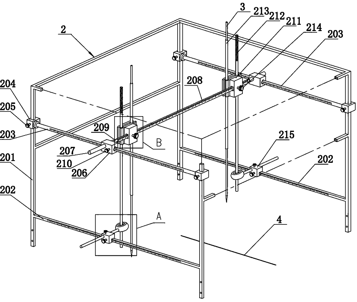
[0025] Example 1: Fixing the pedicle screw 3 in qualitative spinal surgery requires drilling a prefabricated screw track in the bone of the patient's surgical site, and then implanting the pedicle screw 3 along the screw track. The prefabricated nail channel needs the help of such as figure 2 The pedicle screw positioning adjustment device 2 shown is combined with the intraoperative X-ray system in the operating room and the central opaque marking reference line 4 .

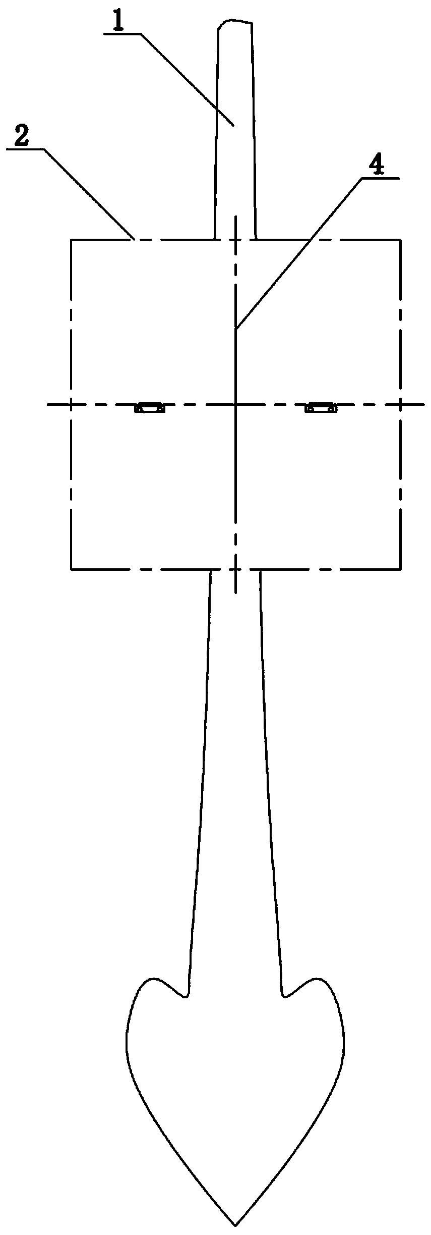
[0026] Determine the entry point of the nail path and the entry angle for drilling prefabrication. The position of the entry point of the nail path is relatively easy to determine, and the entry angle needs to be determined in combination with the X-ray system under fluoroscopy. like figure 1 and Figure 7 As shown, the central opaque marker reference line 4 is located at the center of the spine of the patient’s back, and the angle of the lateral adjustment angle b is determined under the perspective state by ...

Embodiment 2

[0036] Embodiment 2: on the basis of embodiment 1, as Figure 10 As shown, between the front and rear columns 201 on both sides of the fixed frame, the frame lower stringer 202 is set on the lower layer, and the frame upper stringer is set on the upper layer. Moreover, both the frame lower stringer 202 and the frame upper stringer are fixed stringers that are directly fixed on the corresponding column 201 and cannot slide.

Embodiment 3

[0037] Embodiment 3: On the basis of Embodiment 1, the vertically moving upper sliders 206 on both sides are provided with fixed bushings 207 along the transverse direction, and the two ends of an adjusting beam are matched and fitted in the corresponding fixed bushings 207 . In this embodiment, the adjusting beam is cylindrical, and scales are provided on its side.


PUM


Abstract

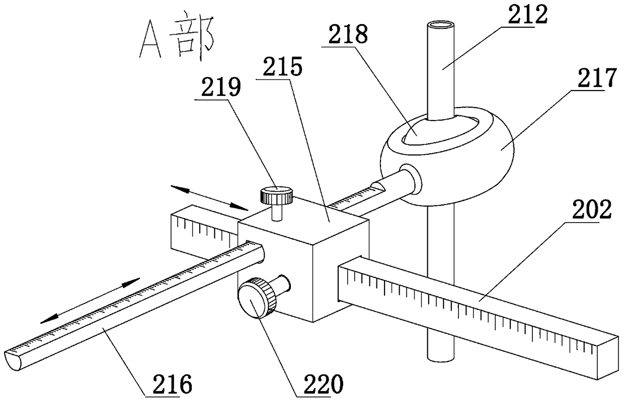
The invention discloses a pedicle screw positioning and adjusting device. Frame lower longitudinal beams and frame upper longitudinal beams are arranged between front and rear uprights on two sides ofa fixing frame, a longitudinal movement slider is mounted on each longitudinal beam in a sleeved manner, a universal ball joint capable of moving transversely is mounted on each longitudinal movementslider, an adjusting cross beam is mounted between the longitudinal movement upper sliders in a sleeved manner, a transverse adjusting mechanism is mounted on the adjusting cross beam in a sleeved manner, a transverse movement slider of the transverse adjusting mechanism is mounted on the adjusting cross beam in a sleeved manner, the transverse movement slider and a rotating block can rotate, thelower end of a toggling hand rod fixed on the rotating block is fixed in an inner ball center radial through hole of the universal ball joint in a sleeved manner, and a pedicle screw is mounted in aguide sleeve fixing groove in a matched and sleeved manner. By constraining and fixing constraining points at the upper end lower ends of a guide sleeve of a pedicle screw, stability of the pedicle screw guide sleeve can be improved, using reliability of the pedicle screw can be improved, and a guarantee is provided for operation safety.

Description

Technical field: [0001] The invention belongs to the technical field of pedicle fixation and positioning in orthopedic surgery, and in particular relates to a pedicle screw positioning adjustment device. Background technique: [0002] At present, spinal internal fixation is usually performed when the spine needs to be corrected for accidents or lesions such as spinal fractures, tumor lesions, spondylolisthesis, and scoliosis. Pedicle screw fixation has become a main way to maintain the stability of the thoracic spine after thoracolumbar surgery. [0003] The development of spinal internal fixation technology has played a huge role in promoting the treatment of many diseases such as spinal trauma, orthopedics and degeneration. The pedicle screw fixation device is a spinal orthopedic fixation system based on pedicle screws. At present, there are many open technical means of the existing pedicle screw fixation devices, which are mainly composed of multiple pedicle screws and c...

Claims


Application Information

Patent Timeline
Patent Type & Authority Applications(China)
IPC IPC(8): A61B17/90A61B17/70
CPCA61B17/7001A61B17/88A61B17/90
Inventor 陈聚伍
Owner 陈聚伍
Why Eureka
Try Eureka