Waste gas treating system

A waste gas treatment and exhaust pipe technology, applied in the direction of dispersed particle separation, chemical instruments and methods, separation methods, etc., can solve the problem of reduced efficiency of the waste gas treatment system, the inability to adjust the air delivery volume of the fan according to the use situation, and the inability of the activated carbon adsorption tower to fully Adsorption treatment and other issues to achieve the effect of preventing damage

Inactive Publication Date: 2018-09-04
杭州绿一环保技术有限公司
View PDF8 Cites 5 Cited by
  • Summary
  • Abstract
  • Description
  • Claims
  • Application Information

AI Technical Summary

Problems solved by technology

[0004] The purpose of the present invention is to provide an exhaust gas treatment system to solve the problem that the existing centrifugal fan for exhaust gas treatment proposed in the above background technology cannot adjust the air delivery volume of the fan according to the use situation. If the air volume is too large, the activated carbon adsorption tower behind will not be able to fully perform the adsorption treatment during the adsorption process. If the air volume is too small, the efficiency of the exhaust gas treatment system will be reduced.

Method used


Image

  • Waste gas treating system
  • Waste gas treating system
  • Waste gas treating system

Examples


Embodiment Construction

[0020] The technical solutions in the embodiments of the present invention will be clearly and completely described below with reference to the accompanying drawings in the embodiments of the present invention. Obviously, the described embodiments are only a part of the embodiments of the present invention, but not all of the embodiments. Based on the embodiments of the present invention, all other embodiments obtained by those of ordinary skill in the art without creative efforts shall fall within the protection scope of the present invention.

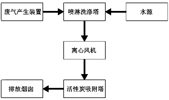
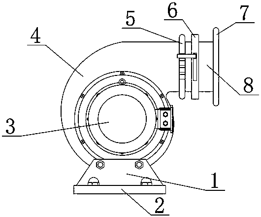
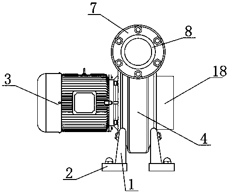
[0021] see Figure 1-5 , the present invention provides a technical solution: a waste gas treatment system, including a spray tower, a centrifugal fan, an activated carbon adsorption tower, a discharge chimney, and a fan casing 4, one side of the fan casing 4 is fixedly connected with a motor 3, and the fan casing The upper side of 4 is fixedly connected with an exhaust pipe 8, one side of the exhaust pipe 8 is provided with an air vo...


PUM


Abstract

The invention discloses a waste gas treating system. The waste gas treating system comprises a spraying tower, a centrifugal fan, an activated carbon adsorption tower, a blowdown stack and a fan casing, wherein a motor is fixedly connected to one side of the fan casing; an exhaust pipe is fixedly connected to the upper side of the fan casing; an air quantity regulating ring is arranged on one sideof the exhaust pipe; a fixed plate is arranged on one side of the air quantity regulating ring and is fixedly connected with the exhaust pipe by screws; a connecting flange is fixedly connected to one end of the exhaust pipe; an inner pore diameter plate is fixedly connected to the inner side of the air quantity regulating ring; an air outlet is formed in the surface of the inner pore diameter plate; an inner revolving ring is arranged on one side of the inner pore diameter plate. The air quantity regulating ring is arranged on the exhaust pipe; when the centrifugal fan is used, baffles rotate to adjust the size of the air outlet by rotating an adjusting rod, so that the problem that air quantity of the centrifugal fan cannot be adjusted is solved.

Description

technical field [0001] The invention belongs to the technical field of waste gas treatment, and in particular relates to a waste gas treatment system. Background technique [0002] Exhaust gas purification mainly refers to the treatment of industrial waste gas such as dust particles, smoke and dust, odorous gases, and toxic and harmful gases generated in industrial places. Common waste gas purification includes factory dust and waste gas purification, workshop dust and waste gas purification, organic waste gas purification, waste gas odor purification, acid-base waste gas purification, chemical waste gas purification, etc. Waste gas treatment equipment mainly refers to a kind of environmental protection equipment that uses different process technologies to protect the environment and purify the air by recycling or removing and reducing the harmful components of exhaust gas, so that our environment is not polluted. [0003] When the existing centrifugal fan for waste gas tre...

Claims


Application Information

Patent Timeline
Patent Type & Authority Applications(China)
IPC IPC(8): B01D53/04B01D53/00
CPCB01D53/00B01D53/0407
Inventor 何佳遥
Owner 杭州绿一环保技术有限公司
Why Eureka
Try Eureka